FT-920 Operating Manual
89
Downloading FT-920 Data
On command, the FT-920 will download some or all
of its operational data. By regular polling of the trans-
ceiver, your software can be kept continuously up-
dated on the status of the FT-920 operating environ-
ment.
The following commands cause the FT-920 to down-
load various components of its operational status:
Status Update
(10H): this Opcode causes the
transceiver to download frequency and memory
channel data, per the parameter data supplied in
the Status Update request (parameters P1 & P4).
Status Flags Request
(FAH): this Opcode in-
structs the transceiver to download eight status
flag bytes.
Read Meter
(F7H): this Opcode causes the trans-
ceiver to download meter deflection data in packs,
pursuant to Note 12 following the “Opcode Com-
mand Chart on page 86.
Pacing
(0EH): this Opcode sets the delay between
bytes of data when you request a download of
data. This delay is set to zero initially, but reset-
ting it to a higher value will allow slower comput-
ers to read and process data returned by the ra-
dio. However, the download time will be signifi-
cantly increased if a high value is used in this
command’s “P1” argument.
These Opcodes are detailed below.
Status Update
(10H)
Depending on the value of parameter P1, this com-
mand will return:
• One byte containing the current Memory
Channel Number (P1=01);
• Two 14-byte records of the current operating
frequency (VFO or Memory; P1-02);
• One each 14-byte record for VFO-A and VFO-
B (P1=03); or
• One 14-byte record of Memory Channel data
(P1=04).
When P1 is set to value 04, parameter
P4
may be
set to a hexadecimal value between 00 and 89 to
prompt the transceiver to download frequency infor-
mation on any of the memories, as shown in Note 7
on previous page. So P1=04 instructs the radio to
download memory data, and P4’s value defines which
memory channel’s data is to be downloaded.
The format for the 14-byte frequency data records is
shown at the end of this sub-section.
Status Flags Request
(FAH)
The format for the eight Status Flags is shown be-
low:
Bit O ffset Stat us Flag Byte #0 Contents
0 Split Operatio n active with VFO-B on TX
1 Split Operation active with VFO-B on RX
2 Antenna Tuner On/tuning
3 CA T System ope ration in progres s
4 VFO-B In Us e (both TX and R X on VFO-B)
5 Direct Keypa d Entry in progress
6VFO-A is Muted
7 Tran smission in progress (PTT line g rounded )
Bit O ffset Stat us Flag Byte #1 Contents
0 5-sec ond "Memory Ch eck" countdown in progress
1 Memory Checking in progres s
2 Dual VFO Tracking active
3 Quick Memory Bank (QMB) selected
4 Memory Tuning in progress
5 VFO Operatio n selec ted
6 Memory Mode selected
7 General Cov erage R eception active
Bit O ffset Stat us Flag Byte #3 Contents
0 Not Used
1 Alpha-Numeric Memo ry Lavel selected
2 Not Used
3 Linear Ampli fier Tuni ng Pulser active
4 PTT grounded via CA T command
5 Transmit "Inhibit" is active
6 Key Release Timer ac tve
7PTT inhibit
Bit O ffset Stat us Flag Byte #4 Contents
0 RTTY space (TX Idle )
1 Not Used
2 All Front Pan el Controls locked
3 Group Memory Mode active
4 Antenna B selected
5 Rx Antenna selected
6 Not Used
7 Not Used
Bit O ffset Stat us Flag Byte #2 Contents
0 Fast Tuning is active
1 Antenna Tuner is in-line
2 VFO-B is locked
3 VFO-A is locked
4 Squelch is closed
5 Up s canning is active
6 Scanning is paused
7 Scanning is active
Bit O ffset Stat us Flag Byte #5 Contents
0VFO-A is muted
1VFO-B is muted
2 Not Used
3 Tx activated via Spot switch comman d
4 Not Used
5 Not Used
6 Antenna Tuner's Wait light is on
7 High SWR detected
Bit O ffset Stat us Flag Byte #6 Contents
0 Dual Watch active
1 Not Used
2 Quick Menu Mode active
3 BUS Y lamp is on
4 Fine Tuning active
5 Not Used
6 VFO -B Tx Mu te act iv e
7 VFO -A Tx Mu te act iv e
Bit O ffset Stat us Flag Byte #7 Contents
0 Not Used
1 Menu Setting in progress
2 CTCSS/Tone Burst active
3 Not Used
4 Not Used
5 Linear Amplifier Tuning Pulse bei ng transmitte d
6 DTMF Tone are being transmitted
7 VOX is active
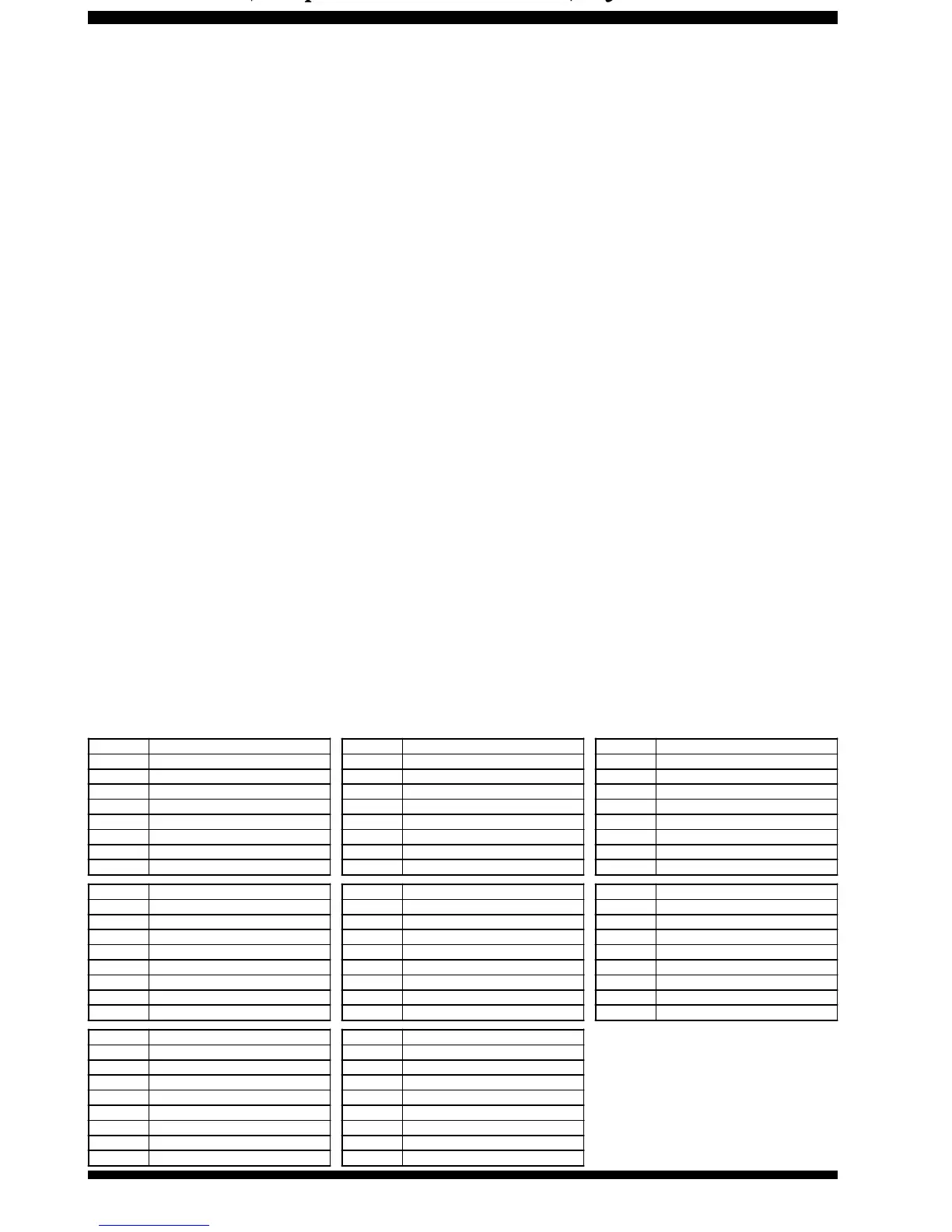
8-Byte Status Flags Record Table
 Loading...