FT-920 Operating Manual
16
2. Digital Modem Interfacing
(TNC, WeatherFax, etc.)
The FT-920 provides several convenient interconnec-
tion points, as well as dedicated operating modes,
for digital operation. While interfacing to commonly-
available modems is simple and straightforward, it is
important that you read the instructions below so as
to understand the facilities that are provided on the
FT-920.
DATA Jack
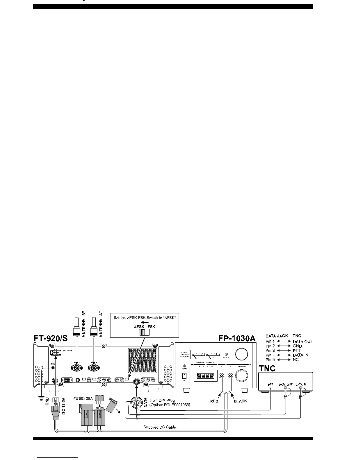
This five-pin DIN connector is the primary interface
port for most digital-mode operation. It provides the
following connection points which may be required in
your installation:
Pin 1 (AFSK Input):
Connect this pin to your TNC’s “AFSK Out” or “Mic
Audio” output line. The optimum input level is 30
mV rms, and the input impedance is 3 kΩ. Your
TNC’s audio output level potentiometer will allow
you to set the level to the optimum value. This pin
may be used either for 300 baud SSB-mode digi-
tal operation or for 1200-baud FM packet. The
bandwidth and frequency response are not, how-
ever, suitable for 9600 baud operation. Be sure
the AFSK-FSK switch on the rear panel is in the
AFSK position.
For FSK operation (whereby the TNC closes a
line to ground to accomplish teletype keying), set
the AFSK-FSK switch to FSK, and connect your
TNC’s FSK keying line to Pin 1.
Pin 2 (Ground):
Connect this to the shield(s) of the cable(s) used
for connections between the TNC and the FT-920.
Pin 3 (PTT):
Connect this pin to the PTT line from the TNC.
This pin, when grounded by the TNC, places the
FT-920 into the Transmit condition.
Pin 4 (Audio Out):
Connect this pin to your TNC’s “RX Audio” input
line. This is a constant-level (100 mV rms @ 600
Ω) audio output line which is
not
affected by the
position of the front-panel AF GAIN control.
Pin 5 (BUSY):
This is a “Squelch Status” pin not generally re-
quired for digital mode operation. This pin is held
at +5V when the squelch is open, and is grounded
when the receiver is muted by the squelch (“no-
signal” condition).
K
EY
Jack (Rear Panel)
If you wish to send CW using your TNC and com-
puter keyboard, the CW Key output line from your
TNC may be connected to the rear-panel KEY jack,
according to the connection information provided on
page 5.
Since a TNC’s keying output is electrically similar to
that of a Straight Key, set the rear panel’s PDL-KEY
switch to the PDL (Manual Key) position, and connect
the TNC’s key line there. You can still connect your
keyer paddle to the
front panel
KEY
jack, and use the
FT-920’s built-in electronic keyer, for those situations
where you wish to send using the paddle; there is no
need to switch the internal keyer on and off.






 To Next Page