FT-920 Operating Manual
88
CAT
Data Protocol
Serial data is passed via the
CAT
jack on the rear
panel of the transceiver at 4800 bps. When data is
being transferred, the
CAT
indicator on the front
panel display is illuminated momentarily, disappear-
ing when the data flow is terminated. All commands
sent from the computer to the transceiver consist of
five-byte blocs, with up to 200 ms between each byte.
The last byte in each block is the
instruction opcode
,
while the first four bytes of each block are arguments
(either parameters for that instruction, or dummy val-
ues required to pad the block out to five bytes).
Each byte sent consists of one start bit, 8 data bits,
no parity bit, and two stop bits:
There are nineteen instruction opcodes for the FT-
920, listed in the chart on page 86. Most of these
duplicate front panel operations, while some replicate
Menu functions. Note that most commands require
one or more parameters to be set; however, regard-
less of the number of parameters present, every
Command Block sent
must
consist of five bytes.
Accordingly, any CAT control program must con-
struct the five-byte block by selecting the appropriate
instruction opcode, organizing the parameters, if any,
and providing unused “dummy” argument bytes to
pad the block to its required five-byte length (the
dummy bytes can contain any value). The resulting
five bytes are then sent,
opcode last
, from the com-
puter to the FT-920 CPU via the computer’s serial
port and the transceiver’s CAT jack.
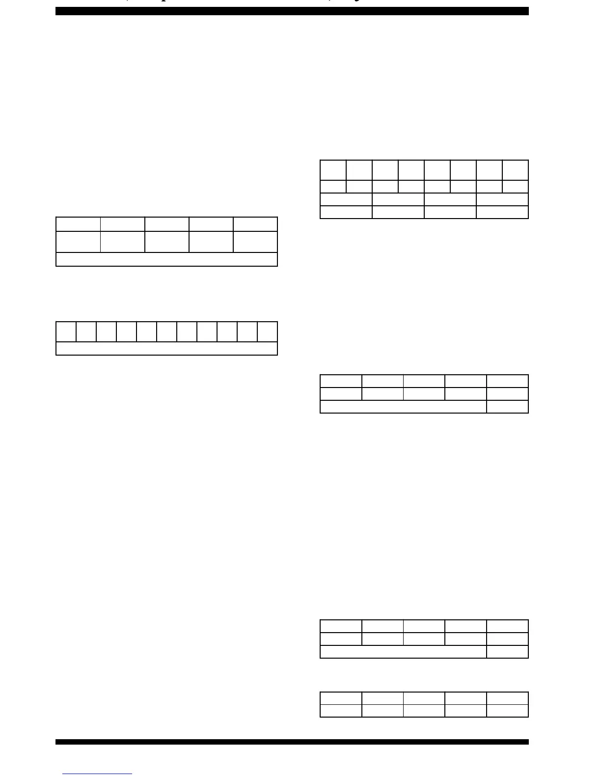
Byte 1 Byt e 2 Byte 3 Byte 4 Byt e 5
Argument Argument Argument Argu ment
Instruction
OPCODE
CAT 5-BYTE COMMAND STRUCTIURE
Start
Bit
01234567
St
o
p
Bit
St
o
p
Bit
CAT DATA BYTE FORMAT
Constructing and Sending
CAT
Commands
Example #1:
Set VFO-A to 14.250.00 MHz
H Per the CAT Command Table, the opcode for “Set
VFO-A Frequency” is “0AH.” Note that the “H”
following each byte value indicate hexadecimal
(base 16) values. Placing the opcode into the fifth
data bit position, we then enter the frequency into
the first four data bit positions:
The four argument byte values are constructed
from the decimal value by breaking the frequency
into 2-digit blocks (in BCD “packed decimal” for-
mat). Leading zeroes
are required
in the hun-
dreds-of-MHz place as well as the tens-of-MHz
place (when below 10 MHz).
H We now insert the four-byte BCD-coded frequency
(00, 50, 42, 01) into the five-byte block along with
the parameter byte, resulting in a complete com-
mand string in hex format:
Send these five bytes to the transceiver, in the
order shown in the table above, left to right:
#" )0
Example #2:
Store the above frequency (14.250 MHz) into Memory
Channel #1-48
H Memory operation is exercised by Opcode 03H.
In base 16 (hexadecimal), Memory Channel #48
is channel 30. And, pursuant to Note #2 associ-
ated with Opcode 03H, parameter P2 (Memory
Set) must be set to value “00.” Therefore, the cor-
responding five-byte command/parameter block
would be !!0.
In sum, commands are sent in the following general
format:
10's
Hz
100's
Hz
1's
kHz
10's
kHz
100's
kHz
1's
MHz
10's
MHz
100's
MHz
00052410
00 50 42 01
Byte 1Byte 2Byte 3Byte 4
Byte 1Byte 2Byte 3Byte 4Byte 5
00 50 42 01 0AH
Data/Argument Bytes Opcode
Byte 1Byte 2Byte 3Byte 4Byte 5
00 00 00 30 03H
Data/Argument Bytes Opcode
Byte 1Byte 2Byte 3Byte 4Byte 5
P4 P3 P2 P1 Opcode






 To Next Page