FT-920 Operating Manual
43
enjoy the many interesting aspects of shortwave lis-
tening. Among the transmission often encountered
are:
International Shortwave Broadcasts
(see table below)
Maritime and Aeronautical Communications
(transoceanic airliners, etc.)
News Services and Diplomatic/Embassy Traffic
Military Communications
WeatherFax Transmissions
(satellite images, charts, and forecasts)
Dealing with Interference
S
HIFT
Control
The front panel’s SHIFT control tunes the position of
the IF passband relative to the frequency of the in-
coming signal in all modes except FM. This allows
the operator to sweep (in effect) the current IF filter
back and forth across the desired signal, eliminating
interference in the process, without changing the pitch
of the incoming signal.
The control is detented in the center (12 o’clock) po-
sition, which represents the “normal” passband cen-
ter frequency. The S
HIFT control is dedicated to the
receive mode, and does not affect your transmitted
signal characteristics (such adjustment of the trans-
mitted signal is, however, provided via Menu Items
U-59, U-60, U-62, and U-63).
Rotate the SHIFT control to the left or right to eliminate
the interference. Careful adjustment of the SHIFT con-
trol may also be useful in improving the recovered
audio on excessively bassy SSB signals. Return the
SHIFT control to the center detented position to return
to the normal default passband setting.
H
IGH
C
UT
/L
OW
C
UT
Controls (DSP)
The DSP system’s chief interference-fighting circuitry
is the passband tuning feature, which features the
HIGH CUT and LOW CUT controls. These controls may
be used to optimize the audio bandwidth so as to
reduce interference and noise, and maximize signal-
to-noise ratio.
To activate the DSP passband filter, press the [DSP]
key (located just below the SHIFT control). The [DSP]
key contains an LED, which will glow green when the
DSP is on. Now rotate the HIGH CUT and LOW CUT to
roll off interference and/or noise, or to enhance the
sound of the incoming signal. A graphical represen-
tation of the relative width of the DSP passband can
be displayed on the Enhanced Tuning Scale by mak-
ing the appropriate configuration of Menu Item U-10.
See page 74 for details.
Press the [DSP] switch again to turn the DSP pass-
band filter off.
Note: Since the DSP passband filter operates in the
audio section, after the AGC detector, very strong
signals inside the IF passband but outside the DSP
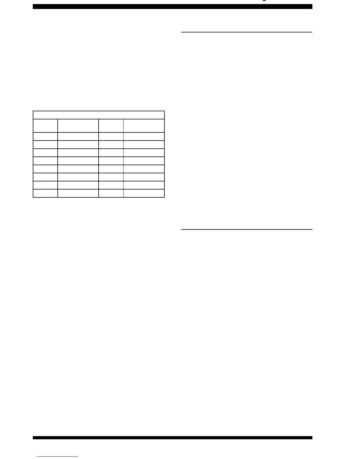
Popular Shotwave Broadcast Bands
Meter
Band
Frequency Range
(MH z)
Meter
Band
Frequency Range
(MH z)
LW 0.150~0.285 31 9.35~9.90
MW 0.520~1.625 25 11.55~12.05
120 2.30~2.50 22 13.60~13.90
90 3.20~3.40 19 15.10~15.70
75 3.90~4.00 16 17.55~17.90
60 4.75~5.20 - 1 8.90~19.30
49 5.85~6.20 13 21.45~21.85
41 7.10~7.50 11 25.67~26.10
 Loading...