6. Remove drive end frame from armature.
If the brush holder (1) must be loosened or re-
moved from the end frame for repairs, the brush
holder must be installed again in the same position.
See Figure 7. Make alignment marks between the
brush holder and the end frame before the brush
mounting plate (4) is released. The brush holder
must be installed again in the same position.
If a new brush holder must be installed, there will
not be an alignment mark on the new brush holder.
Make an alignment mark on end frame with a refer-
ence point on brush holder that must be removed.
Install new brush holder so reference point and
alignment mark are aligned. The new brush holder
must be installed in the same position as the old
holder so the timing will be correct.
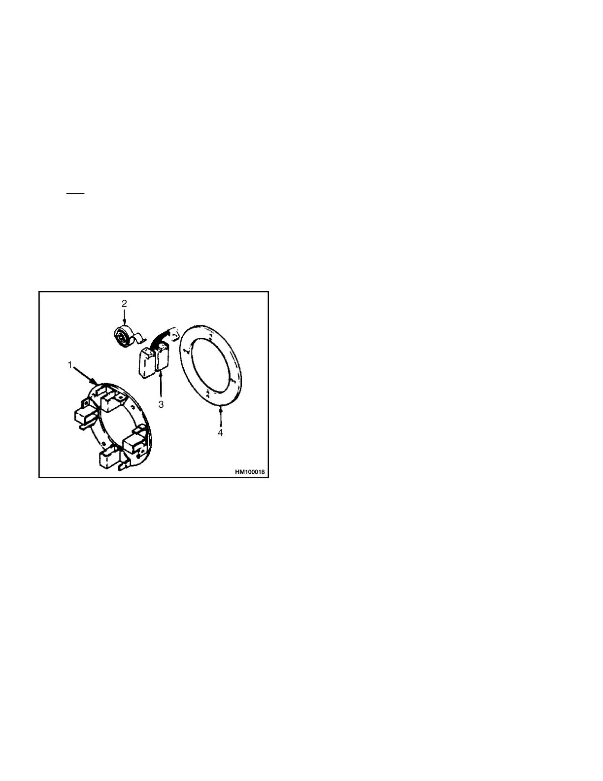
1. BRUSH HOLDER
2. BRUSH SPRING
3. BRUSH
4. BRUSH MOUNTING PLATE
Figure 7. Brush Holder and Mounting Plate
7. Remove screws that fasten brush holder assem-
bly to commutator end frame.
8. Disassemble components of motor as necessary
to make repairs.
Steering Pump Motor
NOTE: Some lift trucks could be equipped with a
Brushless DC Power Steering motor, which is non-re-
pairable.
NOTE: Some electrical trucks use a steering pump
motor. Refer to the service manual for your truck
model for instructions on the removal and installation
of steering pump motors.
1. See Power Steering Motor and Pump for the re-
moval and installation procedures for the steering
pump motor. Make index marks on the steering
pump and the drive end frame of the motor. Re-
move two capscrews that hold steering pump to
motor. Remove pump and allow oil to drain from
drive end frame.
2. Remove brush covers. See Figure 2. Remove two
screws that hold brushes and terminal wires to
brush holders. Pull brush springs out of the way
and pull two brushes from holders.
Motors Repair 0620 YRM 0294
16