1900 YRM 1018 Relief Valve Adjustment
14. Tur n key sw itch t o OFF position. Disconnect the
battery.
15. Discharge the capacitor. See Special Precautions.
16. Remove the pressure gauge and tee.
17. Reconnect the hydraulic hose to pump.
18. Connect the battery and turn the key switch to ON
position.
19. Operate the hydraulic functions several times to
purge the air from the hydraulic circuit.
20. Remove blocks from wheels.
21. Test the lift truck by lifting and lowering a load sev-
eral times. Visually check for leaks.
CAUTION
DO NOT OVERFILL RESERVOIR. Oil will leak from
the breather/filler cap during operation if reservoir
is over filled.
22. Check the hydraulic oil level in the reservoir.
Remove breather cap and add recommended
hydraulic oil to proper level, as required. See
Hydraulic Pump Reservoir.
23. Install the drive unit compartment covers.
RELIEF VALVE ADJUST
Refer to Relief Valve Pressure Check to determine if
adjustment is necessary.
1. Verify the key switch is in the OFF position and the
battery is disconnected.
2. Remove the hydraulic reservoir. See Hydraulic
Pump Reservoir.
3. Loosen the locking nut on the relief valve. See Fig-
ure 6.
4. Adjust the relief valve screw in small increments.
Turn the adjustment screw clockwise to increase
pressure. Turn the adjustment screw counterclock-
wise to decrease pressure.
5. Tighten the lock nut and torque to 15 N•m (11 lbf ft).
6. Install the hydraulic reservoir as removed.
Connect the battery and turn key to ON position.
7. Recheck the relief pressure. See Relief Valve Pres-
sure Check.
8. Repeat as necessary, until the correct relief pres-
sure is measured.
9. Perform Step 13 through Step 23 in Relief Valve
Pressure Check to complete procedure.
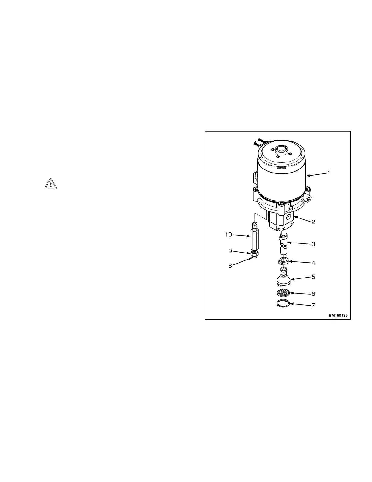
1. LIFT MOTOR
2. PUMP HOUSING
3. TUBE
4. CLAMP
5. INLET ADAPTER
6. SCREEN
7. SNAP RING
8. ADJUSTMENT SCREW
9. LOCK NUT
10. RELIEF VALVE ASSEMBLY
Figure 6. Relief Valve Adjust
11