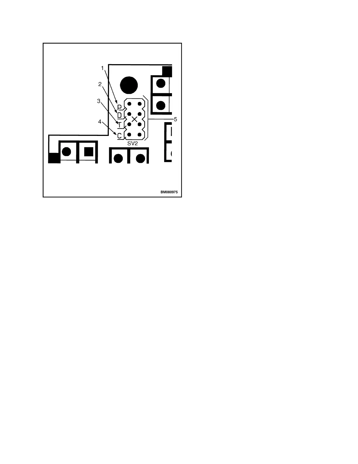
1. P (PARK/ HOME POSITION)
2. D (NOT USED)
3. T (TEACH/CALIBRATE)
4. C (CONFIGURE)
5. JUMPER TERMINAL (SV2)
Figure 14. Jumper Terminal (SV2)
6. Turn the key switch to the ON position and view
the LED display.
7. Press and release the S2 (turtle) switch or S3
(horn) switch to change the number displayed on
the LED to the correct value.
8. Press and release the S (belly) switch to save the
value. A decimal will appear on the LED display
beside the number showing it has been saved.
9. Turn the key switch to the OFF position and move
the jumper to the park (P) position.
10. Turn the key to the ON position and view the LED
to verify the correct number has been saved. The
LED will display the program setting for approxi-
mately five seconds.
Calibrate
Refer to Figure 13 for the following instructions.
1. Verify that the key switch is in the OFF position.
2. Move the jumper from P (park) to T (teach). See
Figure 14.
a. Ensure the leads from the Right Lift switch con-
nects to the JP10 socket and the leads from
the Right Lower switch connects to the JP12
socket. See Figure 13.
b. Ensure the leads from the Left Lift switch (or
shift right switch if equipped with sideshift op-
tion) connects to the JP14 socket and the
leads from the Left Lower switch (or shift left
switch if equipped with sideshift option) con-
nects to the JP15 socket. See Figure 13.
c. Ensure the tiller harness connects to JP1
socket. See Figure 13.
3. Verify that the battery is connected and turn the
key switch to the ON position. The LED will dis-
play a symbol (see Figure 15 view A or B) to sig-
nal that the card is in calibration mode.
2200 YRM 1007 Control Handle
21