Control Handle Arm Proximity Switch
REPAIR
A proximity switch is used to sense the position of the
control handle arm. A target, cast into the base of the
control handle arm moves in front of the proximity
switch when the handle is in the RUN position, acti-
vating the switch and sending a signal to the ZAPI™
Controller. A red LED on the switch illuminates when
the target is sensed. Refer to Brakes 1800YRM1005.
Check and Adjust
Check the proximity switch for proper operation. All
connections must be attached. Take voltage readings
from the back of the connector.
1. Move the lift truck to a safe, level area before per-
forming any repairs.
2. Turn the key switch to the OFF position.
3. Remove the upper drive unit compartment cover.
4. Remove the lower drive unit compartment cover.
5. Remove the four capscrews from the two-piece
shield over the MDU and remove the shields.
6. Turn the key switch to the ON position.
7. Verify battery voltage at the proximity switch con-
nector between pin #1 and pin #2.
8. Place negative lead on the battery (-).
9. Place positive lead on the black wire pin #3 of the
proximity switch connector.
10. Place the control handle arm in the operating po-
sition. Verify that battery voltage is present and
the proximity switch LED is lit.
11. Place the control handle arm in the full up or
down position. Verify that battery voltage is not
present and the proximity switch LED is not lit.
If the proximity switch does not operate properly,
check that the gap measurement is within specifica-
tion and that the wiring harness and connections are
good. Adjust the switch gap if necessary or repair any
wiring problems. If the proximity switch continues not
to function properly, it must be replaced.
Remove
1. Move the lift truck to a safe, level area before per-
forming any repairs.
2. Turn the key switch to the OFF position and dis-
connect the battery.
3. Remove the upper drive unit compartment cover.
4. Remove the lower drive unit compartment cover.
5. Remove the four capscrews from the two-piece
shield over the MDU and remove the shields.
6. Discharge the capacitor. See Special Precau-
tions.
7. Cut the tie wrap located at the end of the proxim-
ity switch harness.
8. Remove the proximity switch harness clamp, lo-
cated beneath the drive unit housing.
9. Disconnect the proximity switch from the wiring
harness.
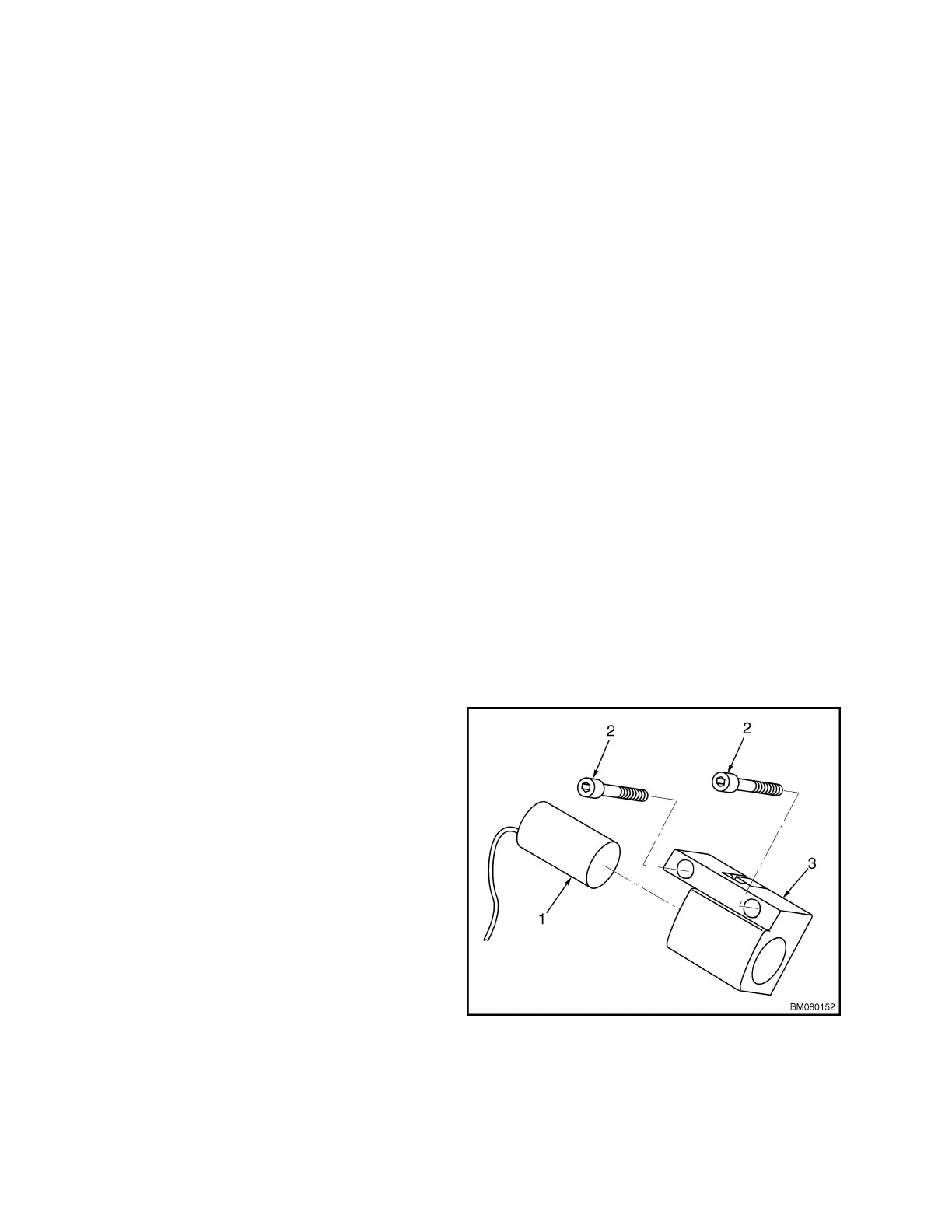
10. Fully lower the control handle arm. Remove the
two capscrews that mount the proximity switch
assembly to the control handle arm. See Fig-
ure 10. Remove the proximity switch assembly.
1. PROXIMITY SWITCH
2. CAPSCREW
3. SWITCH BRACKET
Figure 10. Proximity Switch Assembly
Control Handle Arm Proximity Switch 2200 YRM 1007
16