1900 YRM 1018 Operation
General
The hydraulic system provides the force required to lift
the loads on all motorized lift trucks.
The hydraulic system on the motorized lift truck consists
of the following individual components:
• Pump Motor Assembly
• Hydraulic Pump Assembly
• Solenoid Lowering Valve
• Pilot Relief Valve
• Lift Cylinder
• Reservoir
The hydraulic pump and motor assemblies are mechan-
ically joined together as a compact unit, combining the
reservoir, pump, and motor together as a single assem-
bly. The pump is located inside of the hydraulic tank and
coupled to the motor by an adapter plate, coupler drive,
and four capscrews.
Hydraulic unit servicing is best performed by removing
the unit from the truck to a clean work area.
Operation
LIFTING A LOAD
To raise a load, the lift button must be depressed. De-
pressing this switch will activate the pump motor. This
torque is transferred to the pump from the motor through
the motor shaft and shaft coupling.
Hydraulic oil is pumped through the system as the
pump begins to operate. A vacuum created inside of
the pump draws oil out of the reservoir through the suc-
tion line. Air which is drawn into the reservoir through
the breather displaces the pumped oil, allowing it to
be sent through the system. See Figure 1, Figure 2,
and Figure 3. If the breather is clogged or blocked the
ability of the system to lift a load will be greatly reduced.
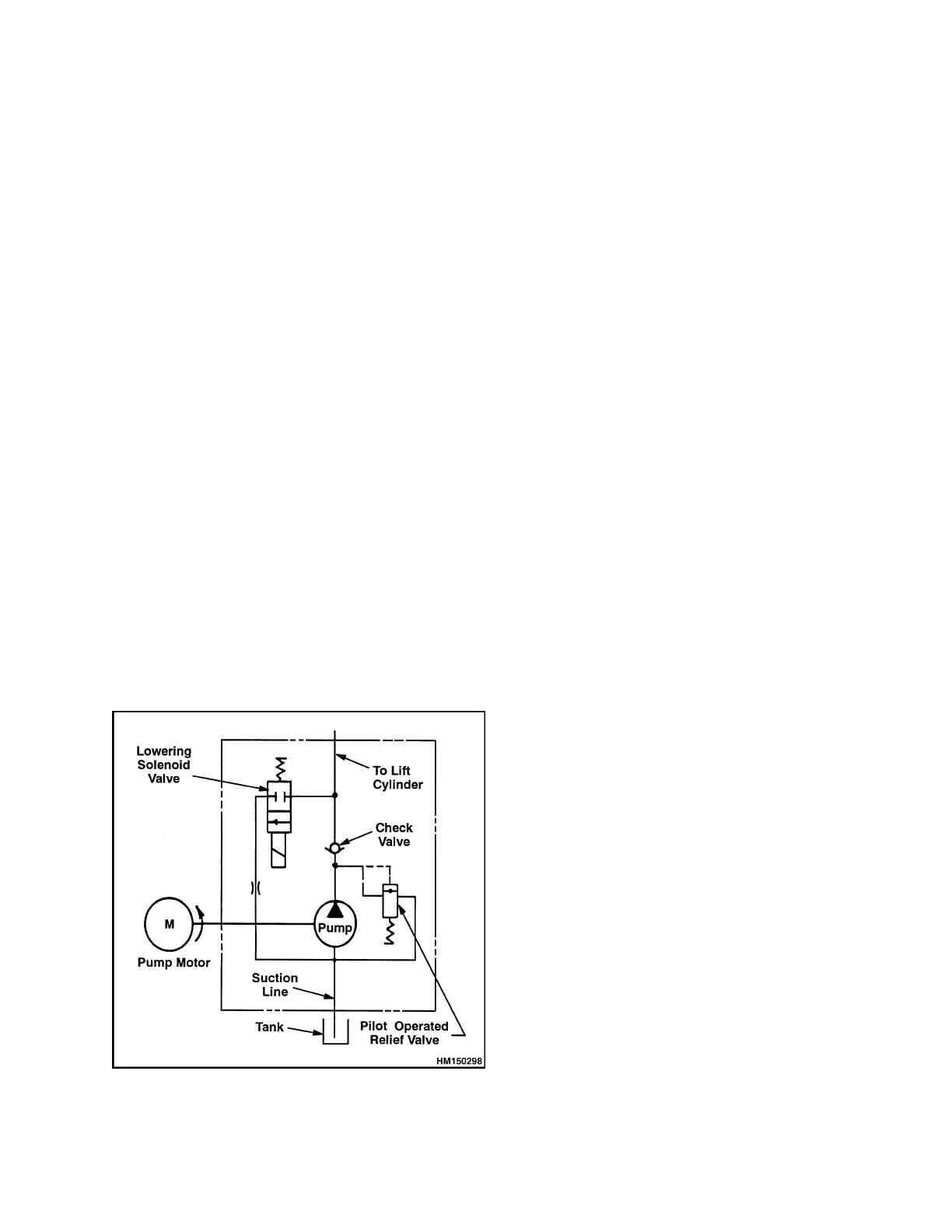
Figure 1. Hydraulic Schematic
As oil is pushed out of the pump, it passes through a
one-way check valve to the lift cylinder. The check valve
prevents oil from flowing back to the pump when lifting
ceases, holding the lift cylinder in the raised position
until lowered.
The piston will begin to lift the load when fluid pressure
acting against it is high enough to overcome the weight
of the load at rest on the forks/platform.
When the piston is fully extended to the end of its stroke
or if the load is too heavy, pressure will continue to
build until the rated pressure needed to operate the
relief valve is reached. When this occurs, the relief
valve, which is normally closed, is forced back against
its spring, creating a path for the fluid to flow back to the
reservoir.
Once relief valve pressure is reached, hydraulic oil will
continue to be diverted from the lift cylinder to the reser-
voir until the lift button is released or electrical power is
interrupted.
LOWERING A LOAD
A load is lowered by depressing the lower button. When
the lower button is depressed, electric current is sent
to the normally closed solenoid lowering valve, which
causes it to change position and open a path for the
trapped hydraulic oil to flow from the cylinder back to
the reservoir.
HYDRAULIC LINES
1. All hydraulic lines must be thoroughly cleaned be-
fore installation.
1