Configure
Refer to Figure 13 for the following instructions.
1. Partially assembly the control handle head. Refer
to Assemble.
2. Connect the control handle card wiring, verify that
the battery is connected, and turn the key switch
to the ON position.
3. The LED will display the program setting for ap-
proximately five seconds. The proper control han-
dle card setting for this model is number 3 for
models MPB040-E and MPW045/050-E or 4 for
models MSW020/025-E and MSW025/030-F. If
the correct number is displayed on the LED, the
control handle card is configured correctly.
4. To begin configuring the card, turn the key switch
to the OFF position.
5. Move the jumper from P (park) to C (configure).
See Figure 14.
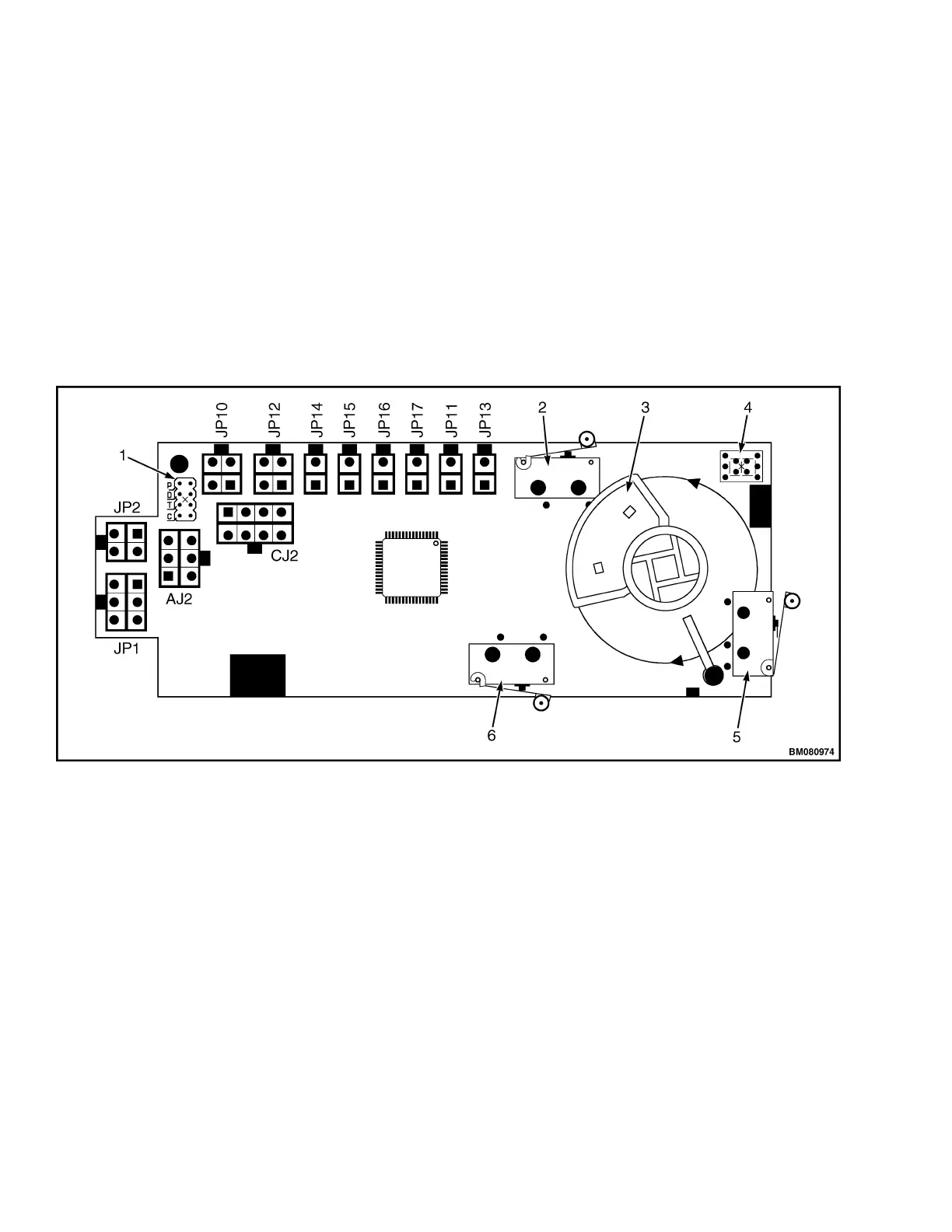
1. JUMPER TERMINALS (SV2)
2. HORN SWITCH (S1)
3. THUMBWHEEL SWITCH (MAGNETIC HOLDER)
4. LED DISPLAY SCREEN
5. BELLY SWITCH (S)
6. TURTLE SWITCH (S2)
Figure 13. Control Handle Card (New Style)
Control Handle 2200 YRM 1007
20