Brush Alignment, Traction and Hydraulic Motors
NOTE: The brush holder in these motors can be rota-
ted for timing of the brush alignment with the commu-
tator. This process normally requires special equip-
ment and training. A special repair service for electric
motors is required to align the bushes for the correct
timing with the commutator. If the brushes are not
timed correctly with the commutator, the motor will
have a low power output. The procedures for timing
an electric motor are not described in this section. Do
not rotate the brush holder from its original position.
If the brush holder must be loosened or removed from
the end frame for repairs, the brush holder must be in-
stalled again in the same position. See Figure 7.
Make alignment marks between brush holder and end
frame before brush mounting plate is released. The
brush holder must be installed again in the same posi-
tion.
If a new brush holder must be installed, there will not
be an alignment mark on the new brush holder. Make
an alignment mark on end frame with a reference
point on brush holder that must be removed. Install
new brush holder so the reference point and the align-
ment mark are aligned. The new brush holder must
be installed in the same position as the old holder so
the timing will be correct.
Tests for Damaged Field and Armature
The tests described in the following paragraphs are to
help a service person check a motor for damage and
to determine if it must be sent to a repair service for
rebuilt motors. The resistance checks will not normally
indicate a short circuit in a motor winding. A resist-
ance greater than 1 to 2 ohms can indicate a dam-
aged winding. The motor must be removed from the
lift truck and disassembled as shown in the illustra-
tions before the tests can be done.
TEST FOR AN OPEN CIRCUIT IN ONE
ARMATURE WINDING
The armature windings in large electric motors nor-
mally have less than 1 ohm of resistance. The two
commutator bars for a winding are found 180 degrees
apart on the commutator. If an ohmmeter (R × 1
scale) is used to check the resistance between the
two commutator bars of the winding, a resistance of
more than 1 ohm indicates a problem in that winding.
A resistance of infinity (∞) indicates an open (dam-
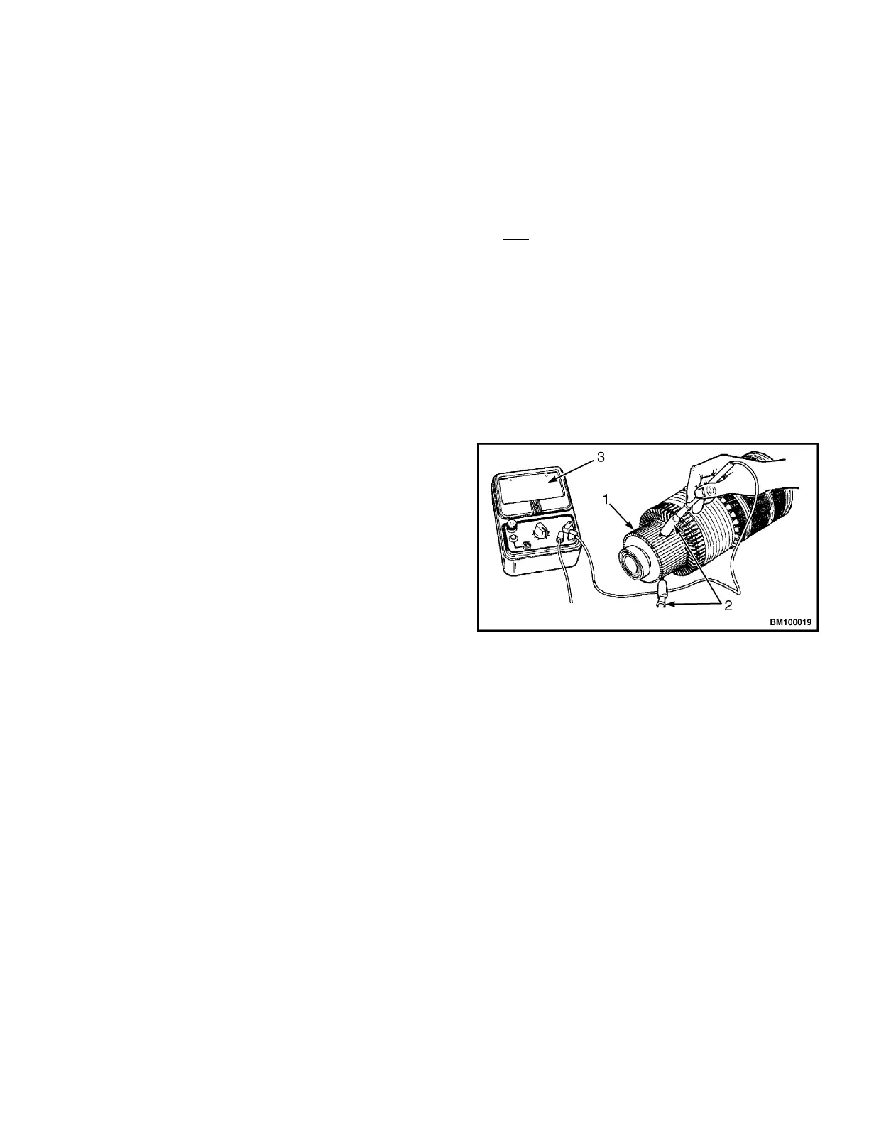
aged) winding. See Figure 14.
If the armature has an open circuit, there will normally
be two burned commutator bars on opposite sides of
the commutator. These burned areas will cause the
brushes to wear rapidly. When the motor operates,
large electric sparks and arcs occur as the damaged
commutator bars rotate under each brush. See Ta-
ble 2.
1. COMMUTATOR BARS
2. TEST PROBES AT 90-DEGREE SEPARATION
3. RESISTANCE SHOULD BE LESS THAN 1 OHM
Figure 14. Test for an Armature Open Circuit
TEST FOR SHORT CIRCUIT IN ONE
ARMATURE WINDING
A short circuit in a motor winding is difficult to test be-
cause of the normal low resistance (less than 1 ohm)
of a good armature. Special equipment is necessary
to check for a short circuit in a motor winding. A motor
with a short circuit in an armature winding will have a
different sound when it begins to operate, but a serv-
ice person must have experience to hear and under-
stand the difference in sound. A winding with a short
circuit will also run hotter than a good winding and
can have indications of heat damage. A winding that
shows heat damage when the other windings are nor-
mal can have a short circuit. See Figure 15.
0620 YRM 0294 Brush Alignment, Traction and Hydraulic Motors
25