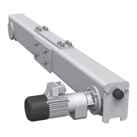
Switching point B↓/B↓↓ (S5/S6) (version 2 only)
(Minimum clearance between B↓ and A↓ 4.7 in.)
1. Lower bottom hook block to 0.39 in. above desired hook position, if necessary turn
setscrew (S5) to the left beforehand. Observe minimum clearance, see Fig. 82.
2. Turn setscrew (S5) to the right until contact S5 switches audibly.
3. Lift and lower bottom hook block until B↓ (S5) is activated.
The following steps apply only for option operational hoist limit switch with pre-switching
for bottom hook position!
Type YK/SK:
1. Lift bottom hook block by 2xb, see Fig. 82, Tab. 35+Tab. 36.
Type YK/SK with VFD:
1. Use formula to calculate clearance 2xb between (B↓↓) and (B↓).
The factory setting of the brake ramp (t) is 1.5 s.
The switching point (B↓↓) is dependent on drum speed (V) and brake ramp (t).
If brake ramp (t) is altered, clearance “b” must be recalculated and reset.
Lift bottom hook block by 2xb.
2. Turn setscrew S6 to the right until contact S6 switches audibly.
3. Check cut-off point at fast and slow speed.
4. Ensure that hoist switches over to slow speed before cut-off point (B↓) is reached.
WARNING Safety hazard. Incorrectly set hoist limit switches may cause serious
accidents. Check operational hoist limit switch for function and correct setting every day.