DTX-MULTI 12
12
6. PN Circuit Board, LCD Module,
VR Circuit Board
6-1 Remove the pad unit R. (See procedure 1.)
6-2 Remove the pad unit F. (See procedure 2.)
6-3 Remove the front case assembly. (See procedure 4.)
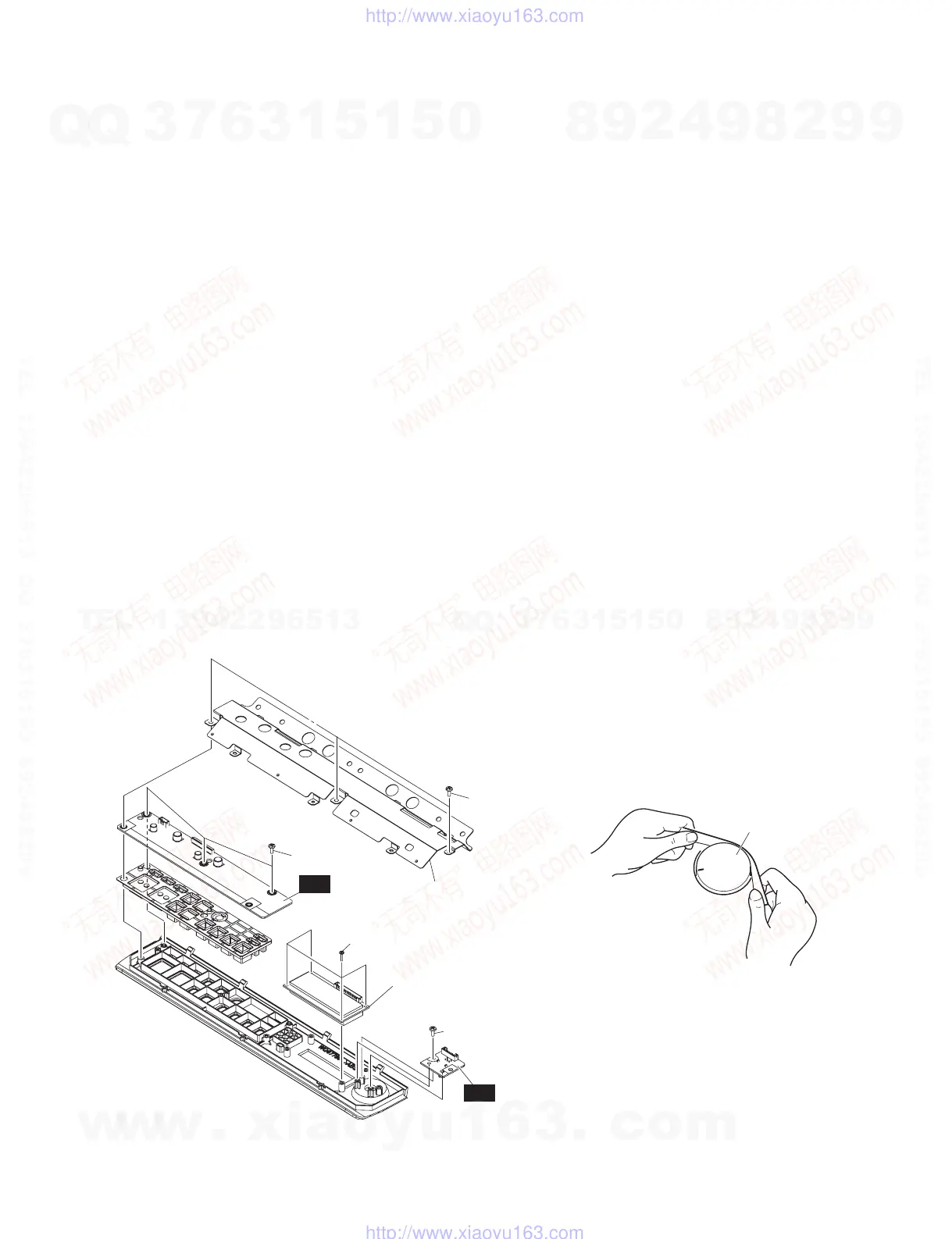
6-4 PN Circuit Board
(Time required: About 5 minutes each)
6-4-1 Remove the three (3) screws marked [80A]. The shield
PN can then be removed. (Fig. 6)
6-4-2 Remove the three (3) screws marked [80B]. The PN
circuit board can then be removed. (Fig. 6)
* Tighten the screws in the order of a, b and c in Fig.
6 when installing the PN circuit board to front case.
(Fig. 6)
6-5 LCD Module
(Time required: About 5 minutes each)
6-5-1 Remove the four (4) screws marked [90]. The LCD
module can then be removed. (Fig. 6)
6-6 VR Circuit Board
(Time required: About 4 minutes each)
6-6-1 Remove the knob V. (Fig. 2, Fig. 7)
6-6-2 Remove the screw marked [80C]. The VR circuit board
can then be removed. (Fig. 6)
6. PN シート、LCD モジュール、VR シート
6-1 パッドユニット R を外します。(1 項参照)
6-2 パッドユニット F を外します。(2 項参照)
6-3 フロント Assy を外します。(4 項参照)
6-4 PN シート(所要時間 :約 5 分)
6-4-1 [80A] のネジ 3 本を外して、シールド PN を外し
ます。(図 6)
6-4-2 [80B] のネジ 3 本を外して、PN シートを外します。
(図 6)
※ PN シートをフロントケースへ取り付ける際は、図6のa,
b,c の順でネジ締めをしてください。(図 6)
6-5 LCD モジュール(所要時間 :約 5 分)
6-5-1 [90] のネジ 4 本を外して、LCD モジュールを外し
ます。(図 6)
6-6 VR シート(所要時間 :約 4 分)
6-6-1 V ツマミを外します。(図 2、図 7)
6-6-2 [80C] のネジ 1 本を外して、VR シートを外します。
(図 6)
• FRONT CASE ASSEMBLY(フロントAssy)
[80A]
[80B]
a
b
c
[90]
[80C]
SHIELD PN
(シールドPN)
LCD MODULE
(LCDモジュール)
PN
VR
[80]: BIND HEAD TAPPING SCREW-B
(Bタイト+BIND)
3.0X8 MFZN2W3 (WE774301)
[90]: BIND HEAD TAPPING SCREW-B
(Bタイト+BIND)
2.6X10 MFZN2W3 (WF741100)
Fig.6
(図6)
KNOB
(Vツマミ)
Fig.7
(図7)
w
w
w
.
x
i
a
o
y
u
1
6
3
.
c
o
m
Q
Q
3
7
6
3
1
5
1
5
0
9
9
2
8
9
4
2
9
8
T
E
L
1
3
9
4
2
2
9
6
5
1
3
9
9
2
8
9
4
2
9
8
0
5
1
5
1
3
6
7
3
Q
Q
TEL 13942296513 QQ 376315150 892498299
TEL 13942296513 QQ 376315150 892498299
http://www.xiaoyu163.com
http://www.xiaoyu163.com