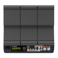
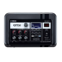
DTX-MULTI 12
24
TEST PROGRAM
Tests item list
No. Item Outline Test Code
01 LCD,LED Check visually if the LCD and LED are turned on. A0 01 00
02 Panel SW Operate the panel switches and check operation. A0 02 00
03 PadSW&Xt IN01
Don’t need check from 03 to 14.
A0 03 00
04 PadSW&Xt IN02 A0 04 00
05 PadSW&Xt IN03 A0 05 00
06 PadSW&Xt IN04 A0 06 00
07 PadSW&Xt IN05 A0 07 00
08 PadSW&Xt IN06 A0 08 00
09 PadSW&Xt IN07 A0 09 00
10 PadSW&Xt IN08 A0 0A 00
11 PadSW&Xt IN09 A0 0B 00
12 PadSW&Xt IN10 A0 0C 00
13 PadSW&Xt IN11 A0 0D 00
14 PadSW&Xt IN12 A0 0E 00
15 PAD SW IN13R1 Check the operation of the external pad [!3] rim switch “A”-compatible circuit. A0 0F 00
16 PAD SW IN13R2 Check the operation of the external pad [!3] rim switch “B”-compatible circuit. A0 10 00
17 Trigger IN13 Check external PAD [!3] Lch including its input level. A0 11 00
18 Trigger IN14 Check external PAD [!4 / !5] Lch including its input level. A0 12 00
19 Trigger IN15 Check external PAD [!4 / !5] Rch including its input level. A0 13 00
20 Trigger IN16 Check external PAD [!6 / !7] Lch including its input level. A0 14 00
21 Trigger IN17 Check external PAD [!6 / !7] Rch including its input level. A0 15 00
22 HiHat Check the operation of the hi-hat pedal-compatible circuit. A0 16 00
23 Foot SW(ftsw)
Check the operation of the foot switch-compatible circuit at [FOOT SW] terminal.
A0 17 00
24 Foot SW(hh)
Check the operation of the hi-hat controller-compatible circuit at [FOOT SW] terminal.
A0 18 00
25 MIDI Check the operation of the [MIDI IN/OUT]. A0 19 00
26 USB-ToDevice Check the operation of the [USB TO DEVICE]. A0 1A 00
27 USB-ToHost Check the operation of the [USB TO DEVICE/TO HOST]. A0 1B 00
28 OUTPUT-L Check the output signal to the [OUTPUT L/MONO] and [PHONES] Lch. A0 1C 00
29 OUTPUT-R Check the output signal to the [OUTPUT R] and [PHONES] Rch. A0 1D 00
30 AUX IN(LR+ph) Check signal input from [AUX IN] for output signal, etc. A0 1E 00
31 AUX IN(ph)
Check signal input from [AUX IN] for output signal, etc. (When outputting to [PHONES] only)
A0 1F 00
32 ROM (IC10) Check the operation of the Program ROM. A0 20 00
33 ROM (IC11) Check the operation of the Wave ROM (P2). A0 21 00
34 ROM (IC13) Check the operation of the Wave ROM (Flash). A0 22 00
35 RAM Check the operation of the SDRAM. A0 23 00
36 Trig(S) IN04 Check the unit PAD [r] including its input level. (For circuit board check) A0 24 00
37 Trig(S) IN05 Check the unit PAD [t] including its input level. (For circuit board check) A0 25 00
38 Trig(S) IN06 Check the unit PAD [y] including its input level. (For circuit board check) A0 26 00
39 Trig(S) IN07 Check the unit PAD [u] including its input level. (For circuit board check) A0 27 00
40 Trig(S) IN08 Check the unit PAD [i] including its input level. (For circuit board check) A0 28 00
41 Trig(S) IN09 Check the unit PAD [o] including its input level. (For circuit board check) A0 29 00
43 FactorySet Executes the Factory Set. A0 2B 00
44 Exit Finishes the test program mode and resets to the normal operation mode. A0 2C 00
w
w
w
.
x
i
a
o
y
u
1
6
3
.
c
o
m
Q
Q
3
7
6
3
1
5
1
5
0
9
9
2
8
9
4
2
9
8
T
E
L
1
3
9
4
2
2
9
6
5
1
3
9
9
2
8
9
4
2
9
8
0
5
1
5
1
3
6
7
3
Q
Q
TEL 13942296513 QQ 376315150 892498299
TEL 13942296513 QQ 376315150 892498299
http://www.xiaoyu163.com
http://www.xiaoyu163.com