xii
Outboard Rigging Guide - 2001 General Rigging Information
Gauge Installation
Digital Instructions
Self-check Function: When the main switch is turned on, all line segments are displayed and the warn-
ing indicator blinks for a few seconds. On twins only with the dual key switch panel, the alarms will self-
check for three beeps.
TESTING GAUGE LIGHT
The 2000~ tachometer requires the Yellow (ignition ON) and the Blue (light wire) to be energized at the
same time for light to activate.
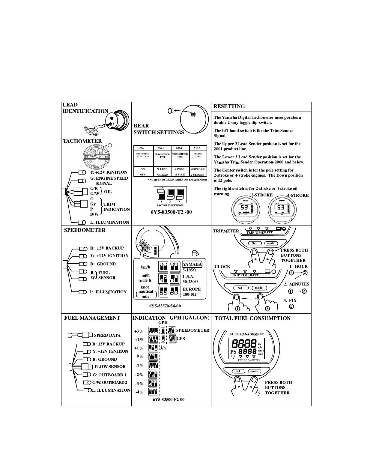
LEAD
IDENTIFICATION
REAR
SWITCH SETTINGS
RESETTING
TACHOMETER
SPEEDOMETER
R: 12V BACKUP
Y: +12V IGNITION
B: GROUND
B
W
}
FUEL
SENSOR
L: ILLUMINATION
FUEL MANAGEMENT
SPEED DATA
R: 12V BACKUP
Y: +12V IGNITION
B: GROUND
FLOW SENSOR
G: OUTBOARD 1
G/W : OUTBOARD 2
L: ILLUMINATION
6Y5-83500-T2 -00
NO.
SW.1
SW.2
SW.3
DIP SWITCH
FUNCTION
TRIM SENSOR
TYPE
TACHOMETER
TYPE
ENGINE
TYPE
ON
*2 LEAD
*3 LEAD
6 POLE
12 POLE
4 STROKE
2 STROKE
OFF
* NUMBER OF LEAD WIRES ON TRIM SENSOR
1
2
3
FACTORYSETTINGS
ON
km/h
mph
(mile h)
knot
nautical
mile
(
)
5-105
Ω
U,S.A.
30-230
Ω
EUROPE
180-0
Ω
6Y5-83570-S4-00
YAMAHA
INDICATION
GPH (GALLON)
SPEEDOMETER
GPS
GPH
+3%
+2%
+1%
0%
-1%
-2%
-3%
-4%
/h
6Y5-83500-F2-00
PRESS BOTH
BUTTONS
TOGETHER
Set
mode
TOTAL FUEL CONSUMPTION
FUEL MANAGEMENT
TTC
ECON
SYNC
l/h
sph
km: l
mpg
TRIPMETER
CLOCK
PRESS BOTH
BUTTONS
TOGETHER
2. MINUTES
3. FIX
1. HOUR
1
1
2
2
1
1
2
Set
mode
Set
mode
TRIP
TIME
BATT
TRIP
TIME
BATT
PS
Y: +12V IGNITION
G: ENGINE SPEED
SIGNAL
G/R
G/W
OIL
}
}
O
Gy
P
B/W
TRIM
INDICATION
L: ILLUMINATION
2-STROKE
4-STROKE
The Yamaha Digital Tachometer incorporates a
double 2-way toggle dip-switch.
The left-hand switch is for the Trim Sender
Signal.
The Upper 2 Lead Sender position is set for the
2001 product line.
The Lower 3 Lead Sender position is set for the
Yamaha Trim Sender Operation-2000 and below.
The Center switch is for the pole setting for
2-stroke or 4-stroke engines. The Down position
is 12 pole.
The right switch is for 2-stroke or 4-stroke oil
warning.
 Loading...