6D93G11
9-18
1
2
3
4
5
6
7
8
9
Self-diagnosis
9
Diagnosing the electronic control
system
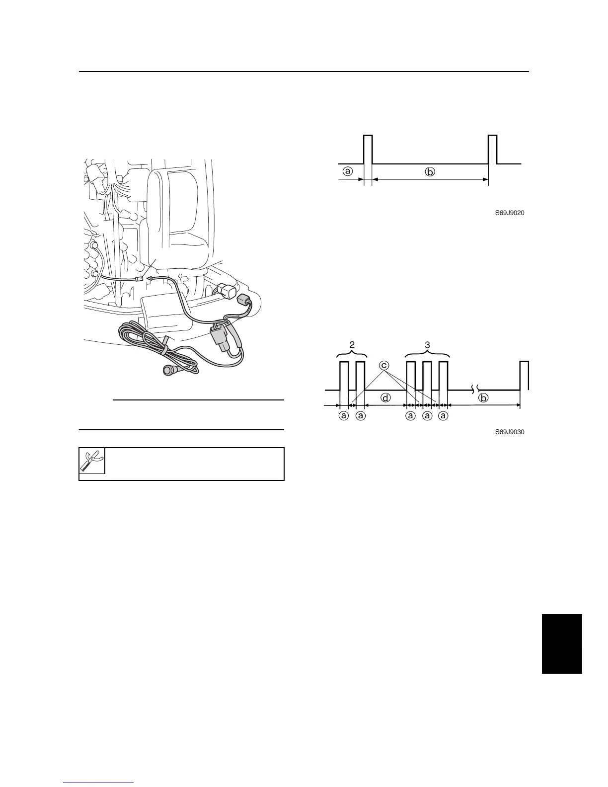
1. Connect the special service tool to the
outboard motor as shown.
NOTE:
When performing this diagnosis, all of the
electrical wires must be properly connected.
2. Start the engine and let it idle.
3. Check the flash pattern of the special
service tool to determine if there are any
malfunctions.
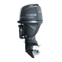
• Normal condition
(no defective part or irregular process-
ing is found)
• Single flash is given every 4.95 sec-
onds.
a
: Light on, 0.33 second
b
: Light off, 4.95 seconds
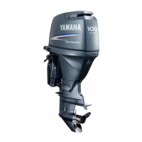
• Trouble code indication
Example: The illustration indicates
code number 23.
a
: Light on, 0.33 second
b
: Light off, 4.95 seconds
c
: Light off, 0.33 second
d
: Light off, 1.65 seconds
Diagnostic flash indicator B:
90890-06865
S6D89030
L/W
Electrical systems / Self-diagnosis