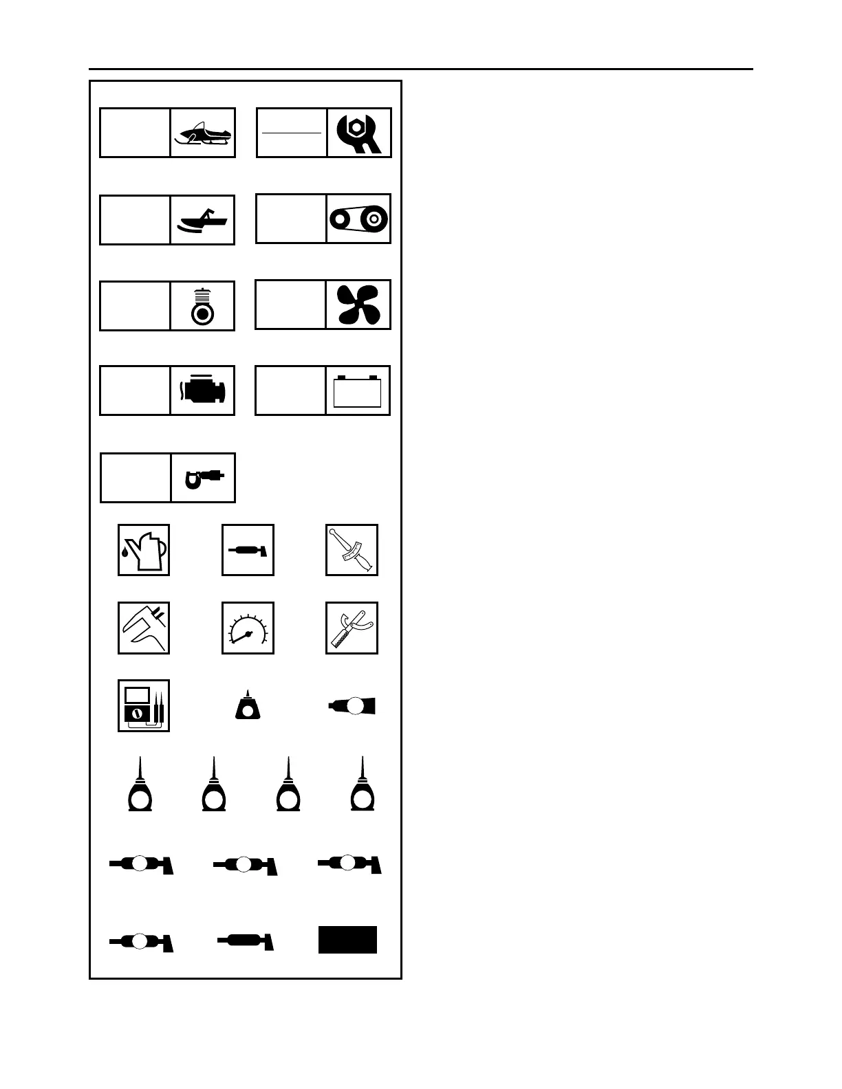
ILLUSTRATED SYMBOLS
(Refer to the illustration)
Illustrated symbols 1 to 9 are designed as thumb
tabs to indicate the chapter’s number and content.
1 General information
2 Periodic inspection and adjustment
3 Chassis
4 Power train
5 Engine
6 Cooling system
7 Fuel injection system
8 Electrical
9 Specifications
Illustrated symbols 0 to F are used to identify the
specifications which appear.
0
Filling fluid
A Lubricant
B Tightening torque
C Wear limit, clearance
D Engine speed
E Special tool
F Electrical data (Ω, V, A)
Illustrated symbols G to R in the exploded diagram
indicate grade of lubricant and location of lubrica-
tion point.
G Apply locking agent (LOCTITE
®
)
H Apply Yamabond No.5
®
I Apply engine oil
J Apply gear oil
K Apply molybdenum disulfide oil
L Apply brake fluid
M Apply wheel bearing grease
N Apply low-temperature lithium-soap-based grease
O Apply molybdenum disulfide grease
P Apply silicone grease
Q ESSO beacon 325 grease or Aeroshell grease #7A
R Use new one
1 2
34
56
78
9
0AB
CDE
FGH
IJKL
MNO
PQR
GEN
INFO
INSP
ADJ
CHAS
POWR
TR
ENG
COOL
FI
–+
ELEC
SPEC
T
R
.
.
LT
5
E
G
M
BF
B
LS
M
S
New
 Loading...