2-12
VALVE CLEARANCE ADJUSTMENT/
THROTTLE BODY SYNCHRONIZATION
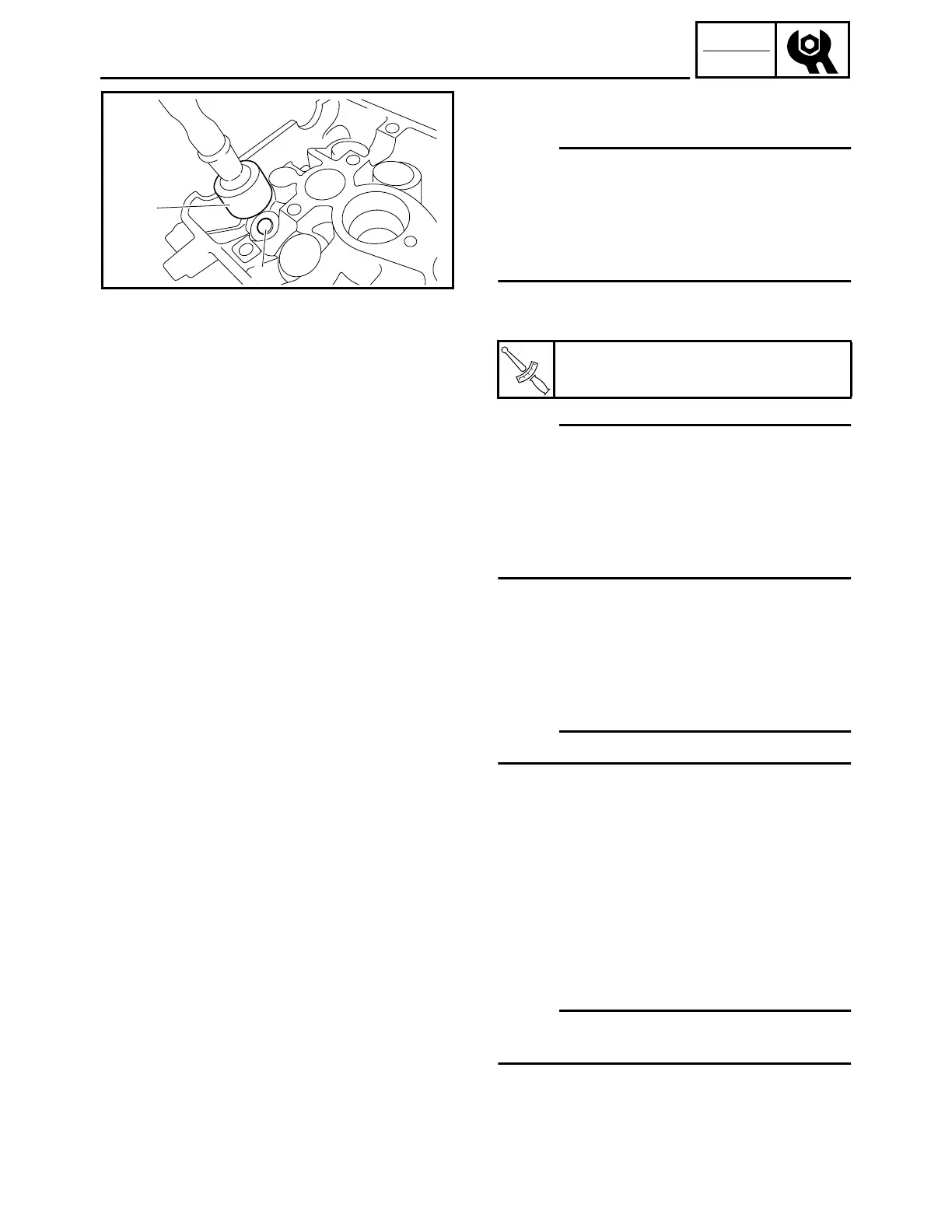
• Install the new valve pad 1 and the valve lifter
2.
NOTE:
• Apply molybdenum disulfide oil to the valve pad
and the valve lifter.
• The valve lifter must turn smoothly when rotated
by hand.
• Install the valve lifter and the valve pad in the cor-
rect place.
• Install the exhaust and intake camshafts, timing
chain and camshaft caps.
NOTE:
• Refer to “CAMSHAFTS” in CHAPTER 5.
• Lubricate the camshaft caps, camshaft lobes,
camshaft journals and camshaft cap bolts.
• Align the camshaft marks with the camshaft cap
marks.
• Rotate the crankshaft clockwise several turns to
seat the parts.
• Measure the valve clearance again.
• If the valve clearance is still out of specification,
repeat all of the valve clearance adjustment
steps until the specified clearance is obtained.
7.Install:
• All removed parts
NOTE:
For installation, reverse the removal procedure.
8.Add:
• Engine oil
Refer to “ENGINE OIL REPLACEMENT”.
T
R
.
.
Camshaft cap bolt:
10 Nm (1.0 m · kg, 7.2 ft · lb)
1
2
THROTTLE BODY SYNCHRONIZATION
NOTE:
Prior to synchronizing the throttle bodies, the valve
clearance should be properly adjusted.
1.Remove:
• Fuel tank
Refer to “SEAT AND FUEL TANK” in CHAP-
TER 5.
 Loading...