7-33
FI
THROTTLE BODY
INSPECTION AND ADJUSTMENT
1.Inspect:
• Throttle position sensor
Inspect steps:
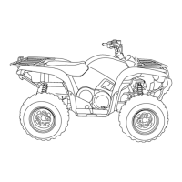
• Disconnect the throttle position sensor coupler.
• Remove the throttle position sensor from the
throttle body.
• Connect the pocket tester (Ω × 1k) to the throt-
tle position sensor.
• Measure the maximum throttle position sensor
resistance.
Out of specification → Replace the throttle posi-
tion sensor.
Positive tester probe
→
Blue terminal
1
Negative tester probe
→
Black/Blue terminal
2
Maximum throttle position sensor
resistance:
2.64 ~ 6.16 k
Ω
at 20 °C (68 °F)
(Blue – Black/Blue)
L
B/L
Y
1
2
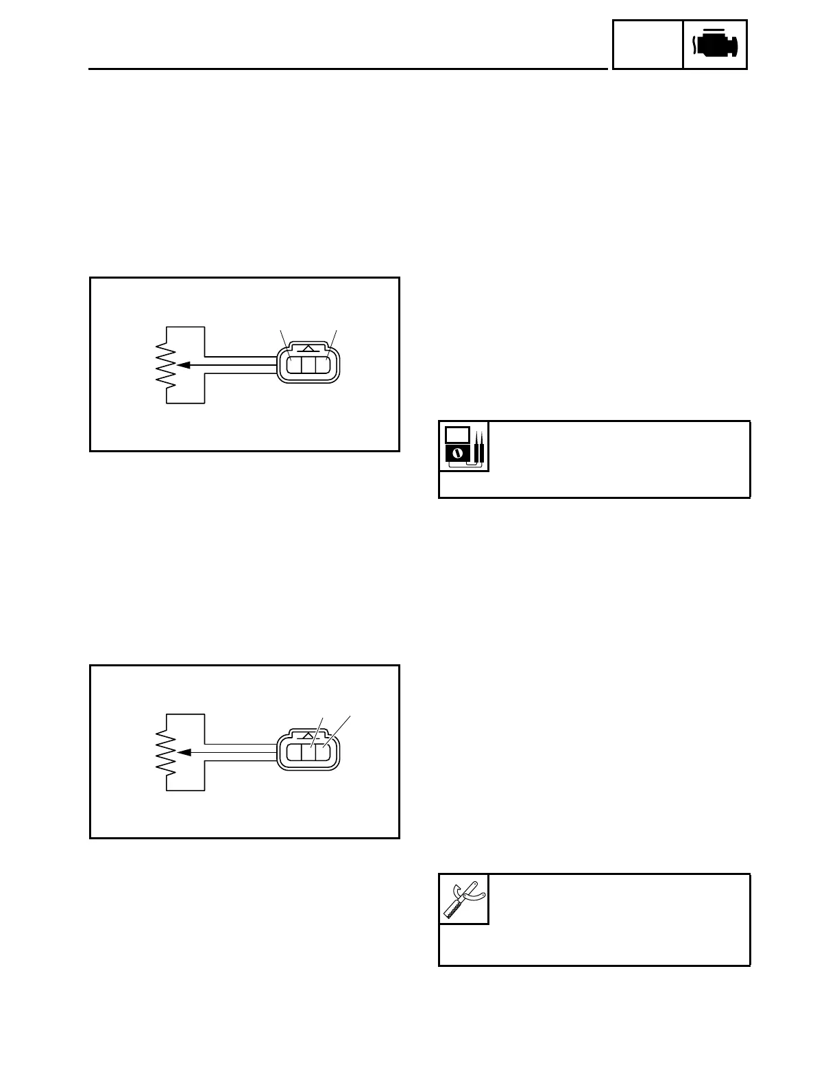
2.Adjust:
• Throttle position sensor angle
Adjustment steps:
• Connect the fuel injection system sub-wire har-
ness coupler to the wire harness.
• Connect the digital circuit tester to the throttle
position sensor.
Positive tester probe
→
Yellow terminal
1
Negative tester probe
→
Black/Blue terminal
2
Digital circuit tester:
90890-03174
Model 88 Multimeter with tachome-
ter:
YU-A1927
L
B/L
Y
1
2