1-7
FEATURES
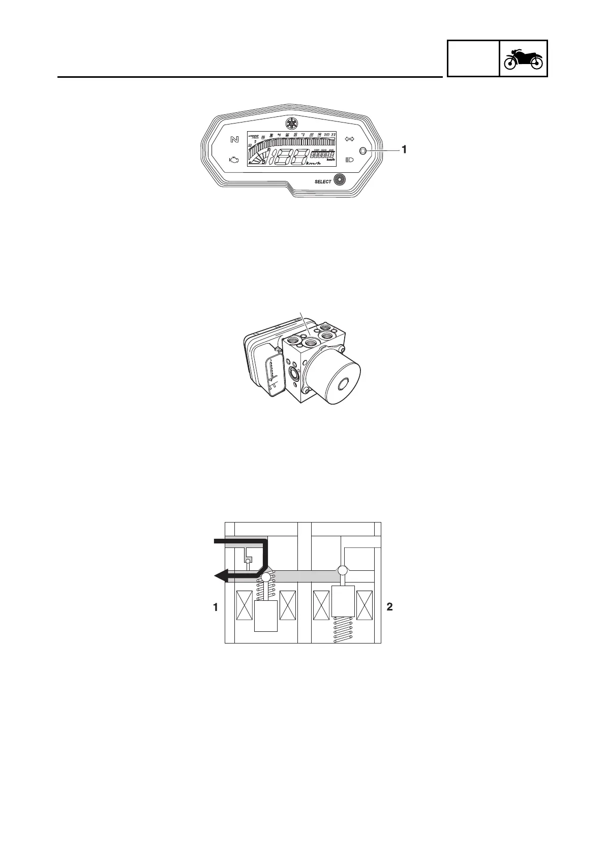
Hydraulic unit assembly
The hydraulic unit assembly “1” is composed of hydraulic control valves (each with a outlet solenoid
val
ve and inlet solenoid valve), buffer chambers, hydraulic pumps, an ABS motor, and ABS ECU. The
hydraulic unit adjusts the front and rear wheel brake fluid pressure to control the wheel speed according
to signals transmitted from the ABS ECU.
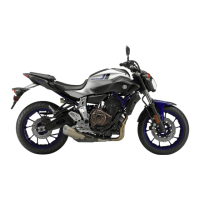
Hydraulic control valve
The hydraulic control valve is composed of a inlet solenoid valve and outlet solenoid valve.
The electromagnetic force generated in the inlet solenoid valve varies proportionally with the duty cycle
control voltage that is supplied to it. Since this voltage is continuously variable, the solenoid valve
moves smoothly and the hydraulic pressure is adjusted linearly.
1. When the brakes are operated normally, the inlet solenoid valve “1” is open and the outlet solenoid
valve “2” is closed. The brake line between the brake master cylinder and brake caliper is open.
2. When the ABS is activated, the inlet solenoid valve “1” closes and the outlet solenoid valve “2” opens
using the power supplied from the ABS ECU signals. This reduces the hydraulic pressure.
3. Brake master cylinder
4. Brake caliper
1
B9X-F8197-E0.book Page 7 Thursday, July 16, 2020 2:28 PM