6-106
ELECTRICAL COMPONENTS
EAS30551
CHECKING THE FUSES
The following procedure applies to all of the fus-
es.
ECA20520
To avoid a short circuit, always turn the main
switch to “OFF” when checking or replacing
a fuse.
1. Remove:
• Rider seat and passenger seat
Refer to “GENERAL CHASSIS” in base ser-
vice manual B97-F8197-E0 on page 4-1.
2. Check:
•Fuse
a. Connect the multimeter to the fuse and
check the continuity.
Set the multimeter selector to “ 1”.
b. If the multimeter indicates “”, replace the
fuse.
3. Replace:
•Blown fuse
a. Set the main switch to “OFF”.
b. Install a new fuse of the correct amperage
rating.
c. Set on the switches to verify if the electri-
cal circuit is operational.
d. If the fuse immediately blows again, check
the electrical circuit.
EWA13310
Never use a fuse with an amperage rating
other than that specified. Improvising or us-
ing a fuse with the wrong amperage rating
may cause extensive damage to the electri-
cal system, cause the lighting and ignition
systems to malfunction and could possibly
cause a fire.
4. Install:
• Rider seat and passenger seat
Refer to “GENERAL CHASSIS” in base ser-
vice manual B97-F8197-E0 on page 4-1.
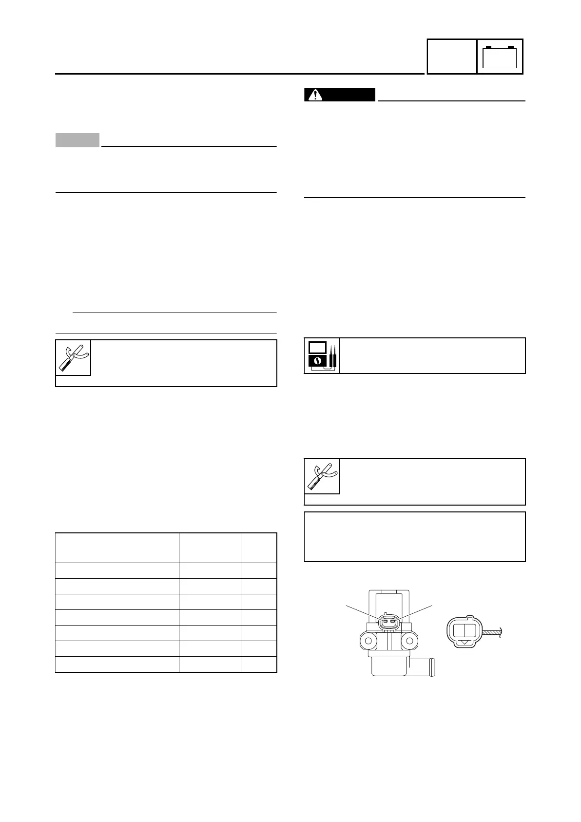
EAS00587
CHECKING THE AIR INDUCTION SYSTEM
SOLENOID
1. 1.Check:
•
Air induction system solenoid resistance
Out of specification Replece.
a. Disconnect the air induction system sole-
n
oid coupler from the air induction system
solenoid.
b. Connect the multimeter ( 1) to the air
induction system solenoid terminal as
shown.
c. Measure the air induction system solenoid
r
esistance.
Multimeter
INS-003
(90890-
03189)
Fuses
Amperage
rating
Q’ty
Main 15 A 1
ABS solenoid 15 A 1
ABS motor 30 A 1
ABS control unit 2 A 1
Spare 30 A 1
Spare 15 A 1
Spare 2 A 1
Solenoid resistance
20-24 at 20° C
Multimeter
INS-003
(90890-03189)
• Positive tester probe
Air induction system solenoid terminal “1”
• Negative tester probe
Air induction system solenoid terminal “2”
Br/R
R/B
21
B9X-F8197-E0.book Page 106 Thursday, July 16, 2020 2:28 PM