3-5
ENGINE
Adjust inlet valve clearance from right side of
the vehicle and exhaust valve clearance from
left side of the vehicle.
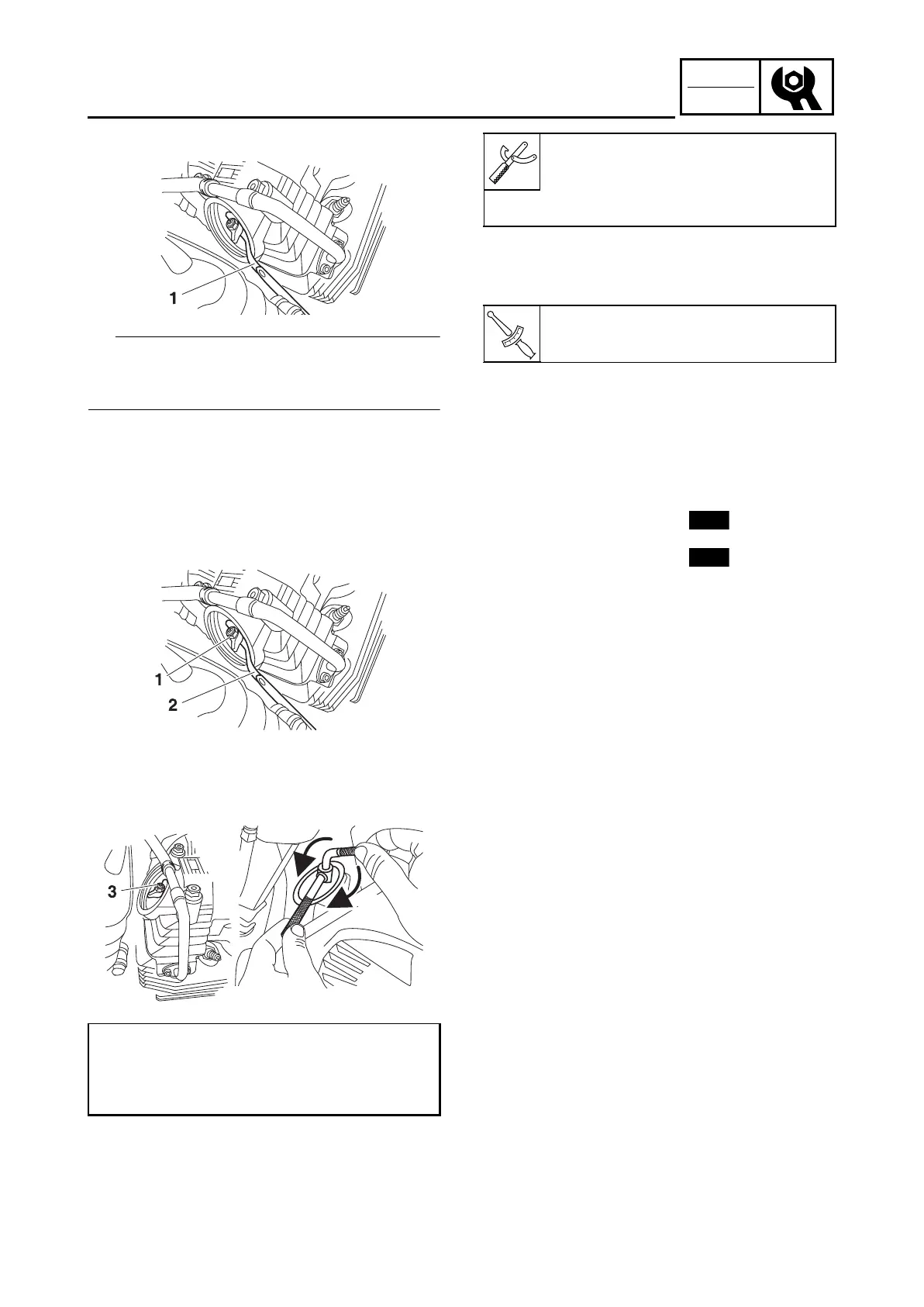
6. Adjust:
• Valve clearance
a.Loosen the locknut “1”.
b.Insert a feeler gauge “2” between the end
of t
he adjusting screw and the valve tip.
c.Turn the adjusting screw “3” in direction
“a
” or “b” until the specified valve clear-
ance is obtained.
d.Hold the adjusting screw to prevent it
fr
om
moving and tighten the locknut to
specification.
e.Measure the valve clearance again.
f. If the valve clearance is still out of specifi-
cation, repeat all of the valve clear
ance
adjust
ment steps until the specified clear-
ance is obtained.
7. Install:
• Crankshaft end accessing screw
(along with the O-ri
ng )
•
Timing mark accessing screw
(along with the O-ring )
8.
Install:
• Cylinder head valve cover along with
O-ring
• Oil cooler
Refer to “OIL COOLER” on page 5-
49 of
base serv
ice manual B97-F8197-E0.
• Fuel tank breather hose
• Canister hose
• Spark plug cap
9. Install:
•
Fuel tank right side and left side panels
Refer to “FUEL TANK” on page 6-1 of
base service manual B97-F8197-
E0.
Direction “a”
Valve clearance is increased.
Direction “b”
Valve clearance is decreased.
Tappet screw holder
YSST-706 (90890-04154)
Tappet adjusting socket
YSST-806A (90890-
04150)
Locknut
14 N·m (1.4 kgf·m, 10 lb·ft)
B9X-F8197-E0.book Page 5 Thursday, July 16, 2020 2:28 PM