14
8 Multi Tap Mod. Delay
8 Multi tap modulation delay.
*n = delay band no.
2 Band Long + 4 Short Mod. Delay
2 band parallel 2 multi tap + 4 band short modulation delay.
*n = delay band no.
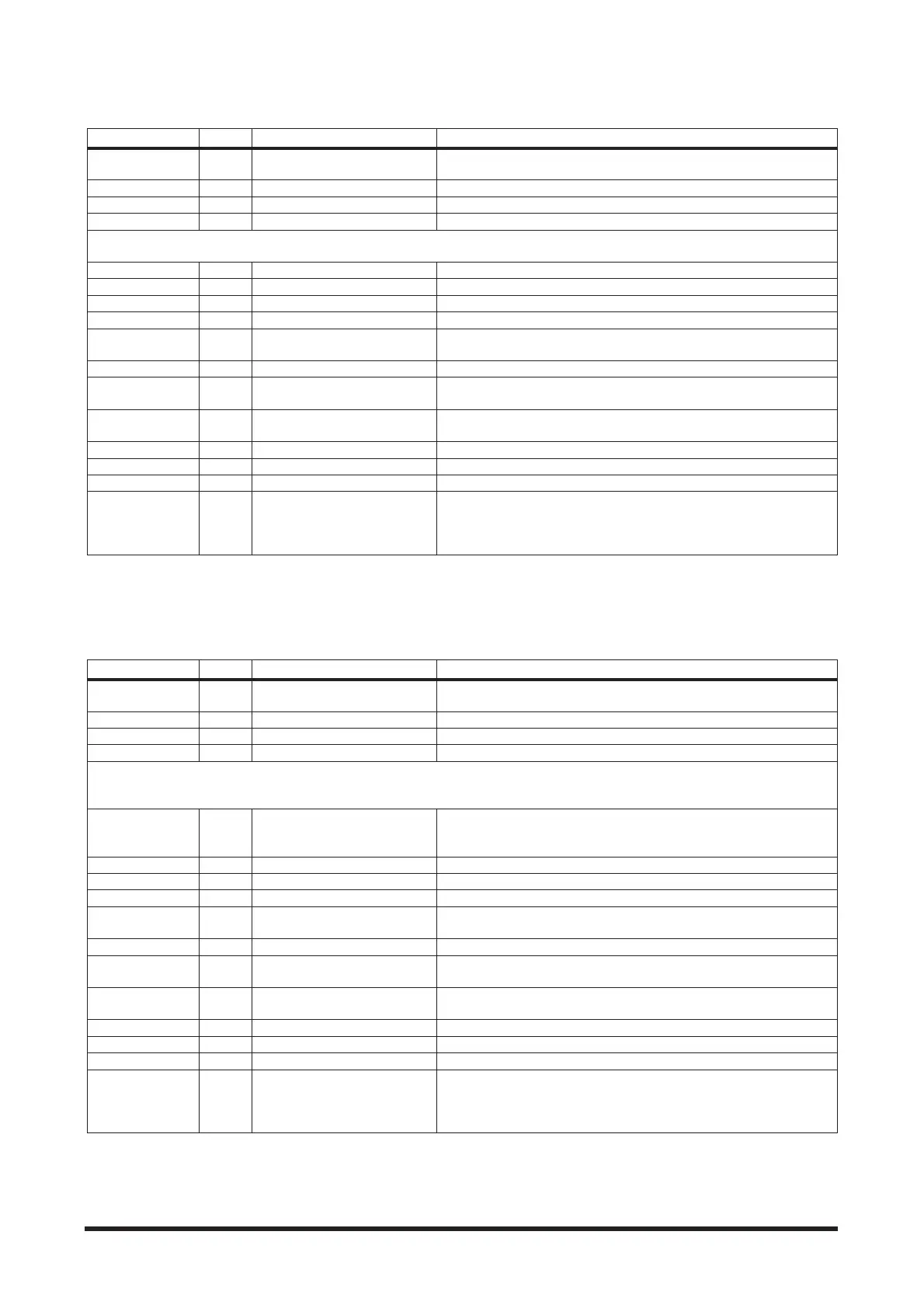
Parameter Display Range Description
Wave Form W.F. Triangle, Saw Up, Saw Down
Selects the modulation waveform used for “other” in the Wave Parame-
ter below.
Effect Level ELVL 0.0 to 10.0 Effect level
Direct Level DLVL 0.0 to 10.0 Level of direct sound
Direct Pan DPAN L10.0 to R10.0 Pan for direct sound
* Edit window page no. corresponds to tap no.
Page1:Tap1, Page2:Tap2, Page3:Tap3, Page4:Tap4, Page5:Tap5, Page6:Tap6, Page7:Tap7, Page8:Tap8
Time DTn 0.5 to 5890.0 ms Delay time (Page1 only)
Low Cut Filter LCFn Off to 10.0 Filter cuts low frequencies (Page1 only)
High Cut Filter HCFn Off to 10.0 Filter cuts high frequencies (Page1 only)
Feedback FBn 0.0 to 10.0 Delay’s feedback level (Page1 only)
Wave WAVn Sine, Other
Modulation waveform. Sine wave or other (“other” is the wave selected
in the Wave Form Parameter above).
Phase PHSn Normal, Reverse Phase of the delay
Tap TAPn 0 to 100 %
The output time of the delay sound in regard to the time of the delay
loop (see page 31)
Speed SPDn 0.0 to 10.0
Modulation speed (modulation phase if the band is synchronized with
another band)
Depth DPTn 0.0 to 10.0 Modulation depth
Pan PANn L10.0 to R10.0 Position in the stereo field of the delay sound.
Level LVLn 0.0 to 10.0 Delay level
Sync SYNn 1 to 8
Setting to synchronize the modulation of different bands (set to any
number other than the band number of the current band, it will syn-
chronize with that band. If set to the same number as the current band,
it will not synchronize.)
Parameter Display Range Description
Wave Form W.F. Triangle, Saw Up, Saw Down
Selects the modulation waveform used for “other” in the Wave Parame-
ter below.
Effect Level ELVL 0.0 to 10.0 Effect level
Direct Level DLVL 0.0 to 10.0 Level of direct sound
Direct Pan DPAN L10.0 to R10.0 Pan for direct sound
* Edit window no. corresponds to delay band no. and tap no.
Page1:Band1 Tap1, Page2:Band1 Tap2, Page3:Band2 Tap1, Page4:Band2 Tap2,
Page5:Band3, Page6:Band4, Page7:Band5, Page8:Band6
Time DTn
Band1, Band2: 0.1 to 1430.0
ms, Band3, Band4, Band5,
Band6: 0.1 to 696.0 ms
Delay time (Page1, Page3, Page5 to Page8)
Low Cut Filter LCFn Off to 10.0 Filter cuts low frequencies (Page1, Page3, Page5 to Page8)
High Cut Filter HCFn Off to 10.0 Filter cuts high frequencies (Page1, Page3, Page5 to Page8)
Feedback FBn 0.0 to 10.0 Delay’s feedback level (Page1, Page3, Page5 to Page8)
Wave WAVn Sine, Other
Modulation waveform. Sine wave or other (“other” is the wave selected
in the Wave Form Parameter above).
Phase PHSn Normal, Reverse Phase of the delay
Tap TAPn 0 to 100 %
The output time of the delay sound in regard to the time of the delay
loop (see page 31)
Speed SPDn 0.0 to 10.0
Modulation speed (modulation phase if the band is synchronized with
another band)
Depth DPTn 0.0 to 10.0 Modulation depth
Pan PANn L10.0 to R10.0 Position in the stereo field of the delay sound.
Level LVLn 0.0 to 10.0 Delay level
Sync SYNn 1 to 8
Setting to synchronize the modulation of different bands (set to any
number other than the band number of the current band, it will syn-
chronize with that band. If set to the same number as the current band,
it will not synchronize.)