9
M.Band Dyna.
3-band dynamics processor, with individual solo and gain reduction metering for each band.
Dyna. Filter
Filter effect. The effect changes according to input level.
Dyna. Flange
Flanger effect. The effect changes according to input level.
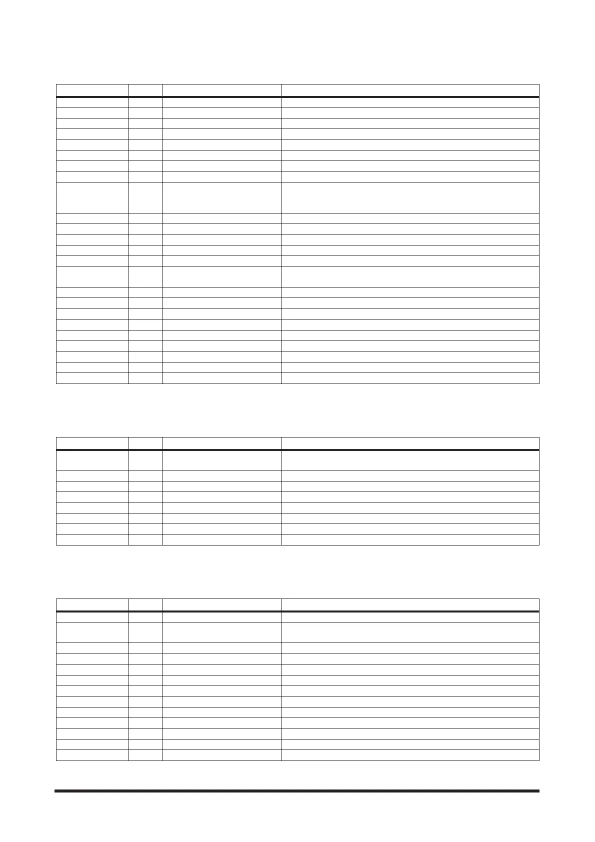
Parameter Display Range Description
Slope SLOP –6, –12 dB Filter slope
Low Gain LO.G –96.0 to +12.0 dB Low band level
Mid Gain MI.G –96.0 to +12.0 dB Mid band level
High Gain HI.G –96.0 to +12.0 dB High band level
Lookup LKUP 0.0 to 100.0 ms Lookup delay
Ceiling CEIL –6.0 to 0.0 dB, Off Specifies the maximum output level
L–M Xover L-MX 21.2 Hz to 8.00 kHz Low/mid crossover frequency
M–H Xover M-HX 21.2 Hz to 8.00 kHz Mid/high crossover frequency
Presence PRE –10 to +10
For positive values, the threshold of the high band is lowered and the
threshold of the low band is increased. For negative values, the oppo-
site will occur. When set to 0, all three bands are affected the same.
Comp. Bypass COMP Off, On Compressor bypass
Comp. Threshold CMPT 24.0 to 0.0 dB Compressor threshold
Comp. Ratio CRAT 1:1 to 20:1 Compressor ratio
Comp. Attack CATA 0 to 120 ms Compressor attack
Comp. Release CREL 6 to 11500 ms Compressor release time
Comp. Knee CKNE 0 to 5
Adjusts the width of the gain curve just above the compressor‘s thresh-
old
Exp. Bypass EXP Off, On Expander bypass
Exp. Threshold EXPT –54.0 to –24.0 dB Expander threshold
Exp. Ratio ERAT 1:1 to ∞:1 Expander ratio
Exp. Release EREL 6 to 11500 ms Expander release time
Lim. Bypass LIM Off, On Limiter bypass
Lim. Threshold LIMT –12.0 to 0.0 dB Limiter threshold
Lim. Attack LATA 0 to 120 ms Limiter attack
Lim. Release LREL 6 to 11500 ms Limiter release time
Lim. Knee LKNE 0 to 5 Adjusts the width of the gain curve just above the limiter‘s threshold
Parameter Display Range Description
Type TYPE
Low Pass Filter, High Pass Filter,
Band Pass Filter
Filter type
Decay DCY 6 to 46000 ms Filter frequency change decay speed
Direction DIR Up, Down Upward or downward frequency change
Sense SENS 0 to 100 Sensitivity
Offset OFST 0 to 100 Filter frequency offset
Resonance RESO 0 to 20 Filter resonance
Level LVL0 to 100 Output level
Mix MIX 0 to 100% Mix level
Parameter Display Range Description
Decay DCY 6 to 46000 ms Decay speed
FB. Gain FB –99 to +99%
Feedback gain (plus values for normal-phase feedback, minus values for
reverse-phase feedback)
Direction DIR Up, Down Upward or downward frequency change
Sense SENS 0 to 100 Sensitivity
Offset OFST 0 to 100 Delay time offset
LSH Freq. LSHF 21.2 Hz to 8.00 kHz Low shelving filter frequency
LSH Gain LSHG –12.0 to +12.0 dB Low shelving filter gain
EQ Freq. EQ.F 100 Hz to 8.00 kHz EQ (peaking type) frequency
EQ Gain EQ.G –12.0 to +12.0 dB EQ (peaking type) gain
EQ Q EQ.Q 10.0 to 0.10 EQ (peaking type) bandwidth
HSH Freq. HSHF 50.0 Hz to 16.0 kHz High shelving filter frequency
HSH Gain HSHG –12.0 to +12.0 dB High shelving filter gain
Mix MIX 0 to 100% Mix level