8
Ring Mod.
Ring modulator.
Mod. Filter
Modulation filter.
Compressor
Compressor.
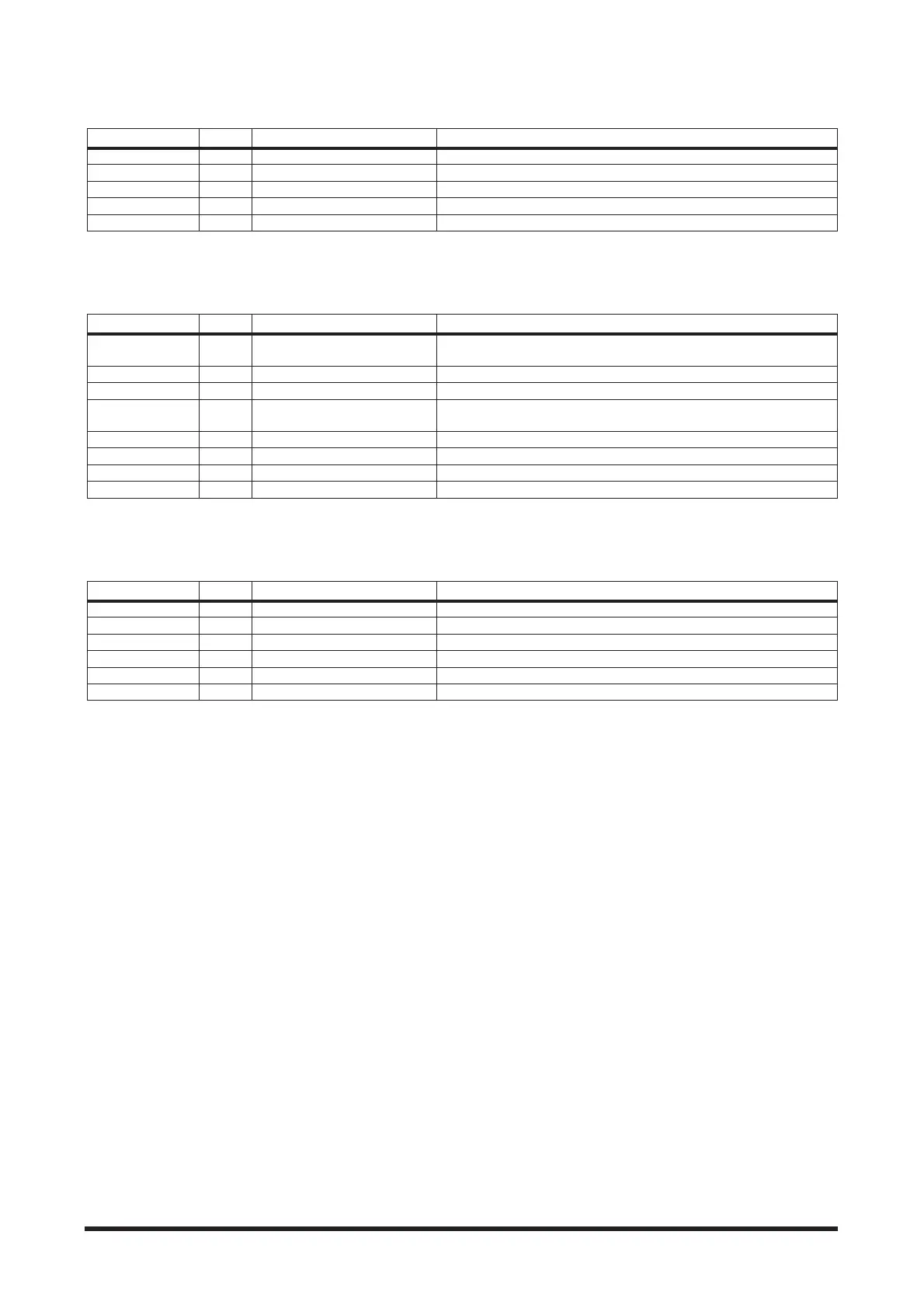
Parameter Display Range Description
Source SRC OSC, SELF Modulation source: oscillator or input signal
OSC Freq. OSC 0.0 to 5000.0 Hz Oscillator frequency
FM Freq. FM.F 0.05 to 40.00 Hz Oscillator frequency modulation speed
FM Depth FM.D 0 to 100% Oscillator frequency modulation depth
Mix MIX 0 to 100% Mix level
Parameter Display Range Description
Type TYPE
Low Pass Filter, High Pass Filter,
Band Pass Filter
Filter type: low pass, high pass, band pass
Freq. FREQ 0.05 to 40.00 Hz Modulation speed
Depth DPTH 0 to 100% Modulation depth
Phase PHAS 0.00 to 354.38 degrees
Left-channel modulation and right-channel modulation phase differ-
ence
Offset OFST 0 to 100 Filter frequency offset
Resonance RESO 0 to 20 Filter resonance
Level LEVL 0 to 100 Output level
Mix MIX 0 to 100% Mix level
Parameter Display Range Description
Comp. Threshold THRE -54.0 to 0.0 dB Level at which compressor activates
Comp. Ratio RATI 1:1 to ∞:1 Compression ratio
Comp. Attack ATAK0 to 120 ms Time required for compressor to peak after exceeding threshold
Comp. Release RELE 6 to 11500 ms Time required for compressor to terminate after going below threshold
Comp. Knee KNEE Hard, 1 to 5 Adjusts the width of the gain curve just above the threshold
Comp. Gain GAIN 0.0 to 18.0 dB Output level