QL5/QL1
44
3. Lithium Battery
(Time required: About 6 minutes)
3-1
Remove the side pad assembly L and R. (See Procedure 1)
3-2 Fix the control panel S assembly. (See procedure 2)
3-3 The lithium battery on the CPUQL circuit board can
be replaced. (Fig. 2, 4)
* Before replacing the lithium battery, be sure to save
all the internal setting data in on a USB memory.
*
After removing or replacing the lithium battery, be sure
to reset the time and date of the clock built in this unit.
Owner’s Manual: Other functions/Setting the date
and time of the internal clock (See page 45).
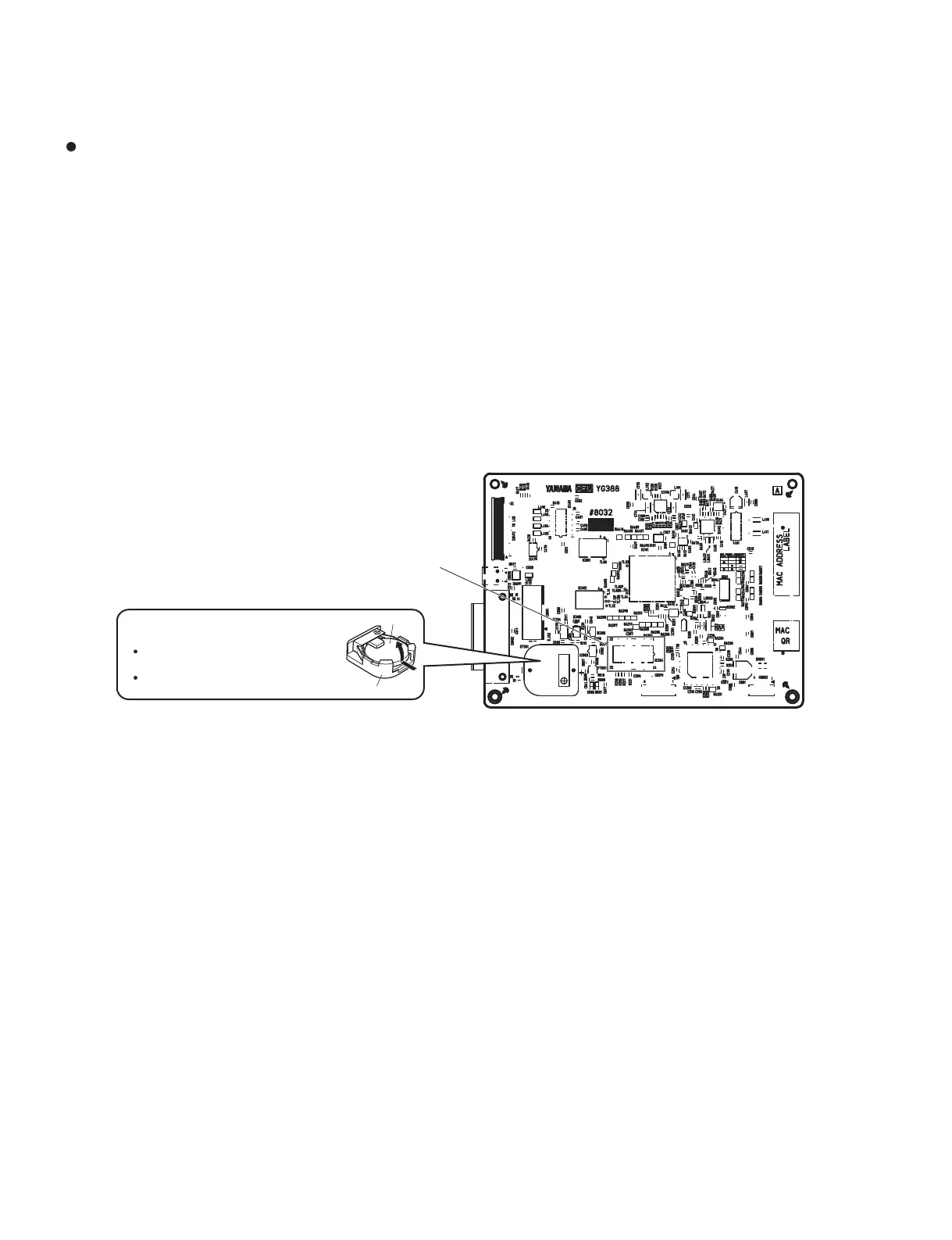
r-JUIJVN#BUUFSZ(リチウム電池)
Battery VN103500
WR846000 (Battery holder for VN103500)
Notice for back-up battery removal. Push the battery
as shown in figure, then the battery will pop up.
Druk de batterij naar beneden zoals aangeven in de
tekening, de batterij springt dan naar voren.
Battery
Battery holder
r$162-$JSDVJU#PBSE(CPUQLシート)
IC204
Fig. 4
(図4)
●コンパネ SAss'y の設置注意
パネル面を下にして置く時は、ノブ等が床に当たり、
変形したり傷が付かないように置いてください。
3. リチウム電池
(所要時間:約 6 分)
3-1 サイドパッド Ass'yL,R を外します。(1 項参照)
3-2 コンパネ SAss'y を固定します。(2 項参照)
3-3 CPUQL シート上より、リチウム電池を交換す
ることができます。(図 2、4)
※ リチウム電池の交換を行う前には、内部の全ての設定
データを USBメモリーにセーブ(保存)してください。
※ リチウム電池の取り外し、または交換した際は、本機
の内蔵時計の日時を合わせてください。
取扱説明書:その他の操作 /内蔵時計の日時を合わせ
る(45ページ参照)
A. ボトム SAss'y の分解
A-1. CPUQL シート
(所要時間:約 6 分)
A-1-1 サイドパッド Ass'yL,R を外します。(1 項参照)
A-1-2 コンパネ SAss'y を固定します。(2 項参照)
A-1-3 [700A] のネジ 4 本を外して、CPUQL シートを
外します。(図 5)
※ CPUQL シートの IC204:MRAM(Magnetoresistive
RandomAccessMemory:磁気抵抗ランダム・アクセ
ス・メモリー)は、磁気に弱いため、ドライバーなど
磁気を帯びたものを近づけないでください。検査時な
ど通電中は、ドライバーなど磁気を帯びたものを 3cm
以内に近付けないでください。(図 4)
※ CPUQL シートには、MAC(Media AccessControl)
アドレスが設定されています。CPUQL シートを交換
すると、MAC アドレスが変更されます。
※ リチウム電池は、CPUQL シートの構成部品ではあり
ません。CPUQLシートを交換する際には、CPUQLシー
トからリチウム電池を取り外して、新しいシートに取
り付けてください。(3 項参照)
Precaution in handling the control panel S assembly
When placing the assembly with its panel face facing down,
be careful so that the control knobs do not contact the fl oor.
A. Disassembly Procedure of Bottom
S Assembly
A-1. CPUQL Circuit Board
(Time required: About 6 minutes)
A-1-1
Remove the side pad assembly L and R. (See Procedure 1)
A-1-2 Fix the control panel S assembly. (See procedure 2)
A-1-3 Remove the four (4) screws marked [700A]. The
CPUQL circuit board can then be removed. (Fig. 5)
* IC204 on CPUQL circuit board: MRAM (Magneto
resistive Random Access Memory) is a storage element
using magnetism. Keep any magnetic item such as a
screwdriver away from it as the magnetic force of such
item may cause damage to the data of IC204 and the
IC itself. (Fig. 4)
* MAC (Media Access Control) address is stored in the
CPUQL circuit board. If the CPUQL circuit board is
replaced, MAC address will be changed.
* The lithium battery is not part of the CPUQL circuit
board. When replacing the CPUQL circuit board,
remove the lithium battery from the CPUQL circuit
board, and install it on the new circuit board.
(See procedure 3)

 Loading...


