Yamatake Corporation Operation of the Transmitter
ST3000 Smart Transmitter Series 900 Electronic Differential Pressure/Pressure Transmitter 5-29
How to display measured value
The following conditions are assumed here:
• Low limit of setting range : 50 kPa
High limit of setting range: 0 kPa
• Input differential pressure of transmitter : 25 kPa
In this case, the output is 50%.
• If the input and output values are inconsistent, check the range and per-
form calibration again. If they are still inconsistent, use the troubleshoot-
ing procedure explained in "Chapter 7 : Maintenance and
Troubleshooting".
• If the displayed data value is unstable, adjust the damping time constant
by referring to "6-7-10 : Display or Change Damping Time Constant".
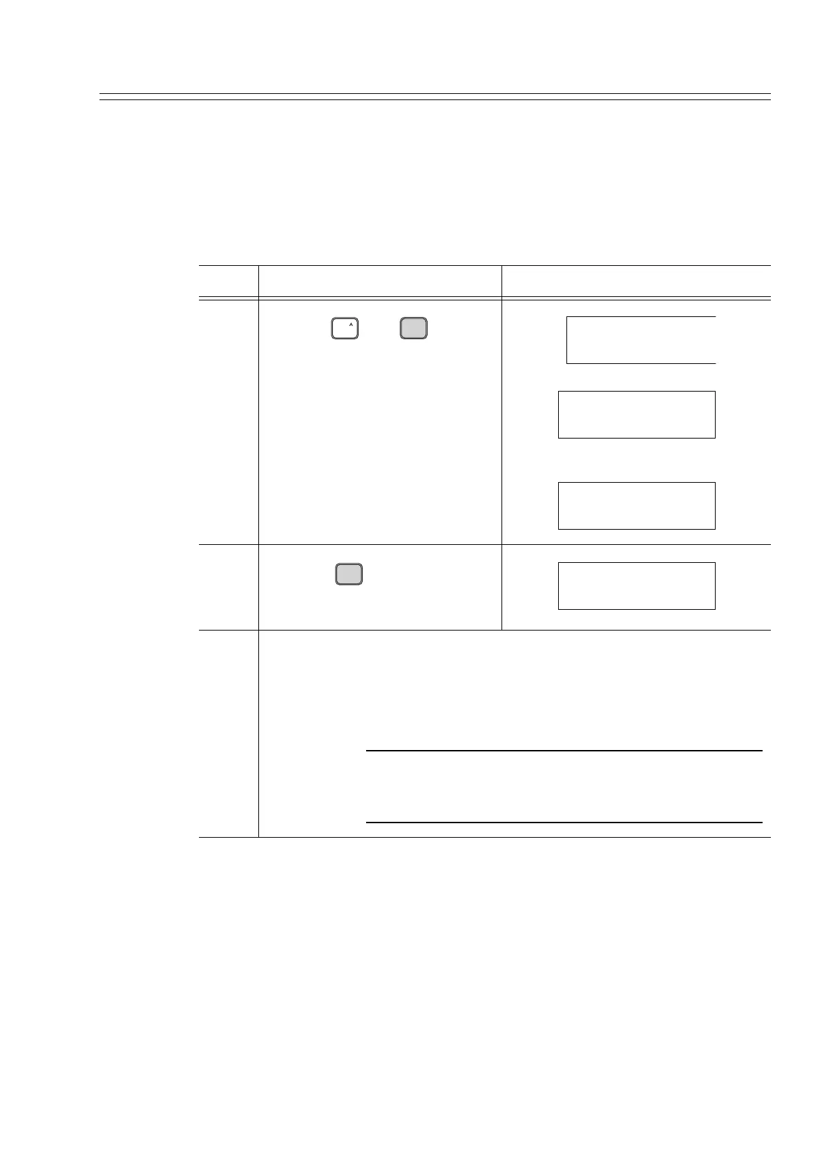
Step Description SFC screen
4
Press the and keys in
that order.
5
Press the key.
6 After completing measurements, remove the clip from the communication
cable and switch the process to regular operation.
CAUTION
Close the cover of the transmitter case securely. Imperfect
closure allows entry of water, damaging internal terminals
and the electronics module.
SHIFT
OUT-
J
PUT
INPUT
SHIFT-
INPUT FIT-1234
WORKING...
INPUT FIT-1234
25.00 kPa
OUT-
J
PUT
INPUT
OUTPUT FIT-1234
50.00 %