Yamatake Corporation Operation of the Transmitter
ST3000 Smart Transmitter Series 900 Electronic Differential Pressure/Pressure Transmitter 5-9
5-3 : Measurement with STD type
5-3-1 :Flow Rate Measurement
5-3-1-1 Preparation for Measurement
WARNING
• Make sure that the process is in the manual control mode.
If in automatic control mode, switch to manual control before starting the follow-
ing procedures.
• Drain poisonous fluids with care, making provisions to protect personnel.
• Always close the differential pressure output valve (main valve), the
drain valve, the gas vent plug (refer to figures 4-8 and 4-9) and the high
pressure side and low pressure side stop valves of the 3-way manifold
valve. Also, open the equalizer valve of the 3-way manifold valve.
Procedure 1
Lead process pressure into the pressure receiving part of the transmitter, using this
procedure:
Step Description
1 Gradually open the main valves of both the high-pressure side and the
low-pressure side (Refer to Figure 4-8 and Figure 4-9). Lead process fluid
into the connecting pipe.1
2 Fill with process fluid, the pressure-receiving part of the transmitter.
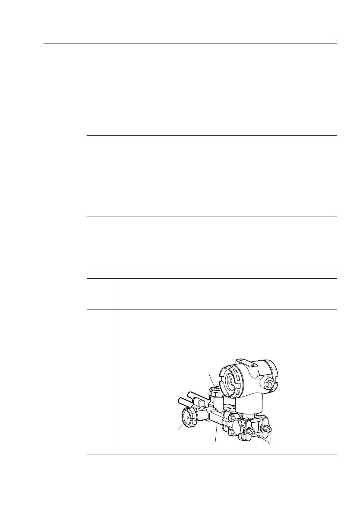
1. Gradually open the high pressure side stop valve. Close, after the pres-
sure receiving part has completely filled with process fluid.
2. Gradually open the low pressure side stop valve. Close, after the pres-
sure receiving part has completely filled with process fluid.
(Equalizer valve)
High-pressure side
Low-pressure side
Low-pressure side
stop valve
3-way manifold valve
Vent / Drain plug
( )