Operation of the Transmitter Yamatake Corporation
5-14 ST3000 Smart Transmitter Series 900 Electronic Differential Pressure/Pressure Transmitter
How to display measured value
The following conditions are assumed:
Low limit of setting range: 0 kPa
High limit of setting range: 50 kPa
Input differential pressure of transmitter: 25 kPa
In this case, the output is 50%. (Linear output)
• If input and output values do not match, check the range and recalibrate.
If after recalibration, they remain inconsistent, troubleshot the transmitter
as described in "Chapter 7 : Maintenance and Troubleshooting".
• If the displayed data value is unstable, adjust the damping time constant
Refer to "6-7-10 : Display or Change Damping Time Constant".
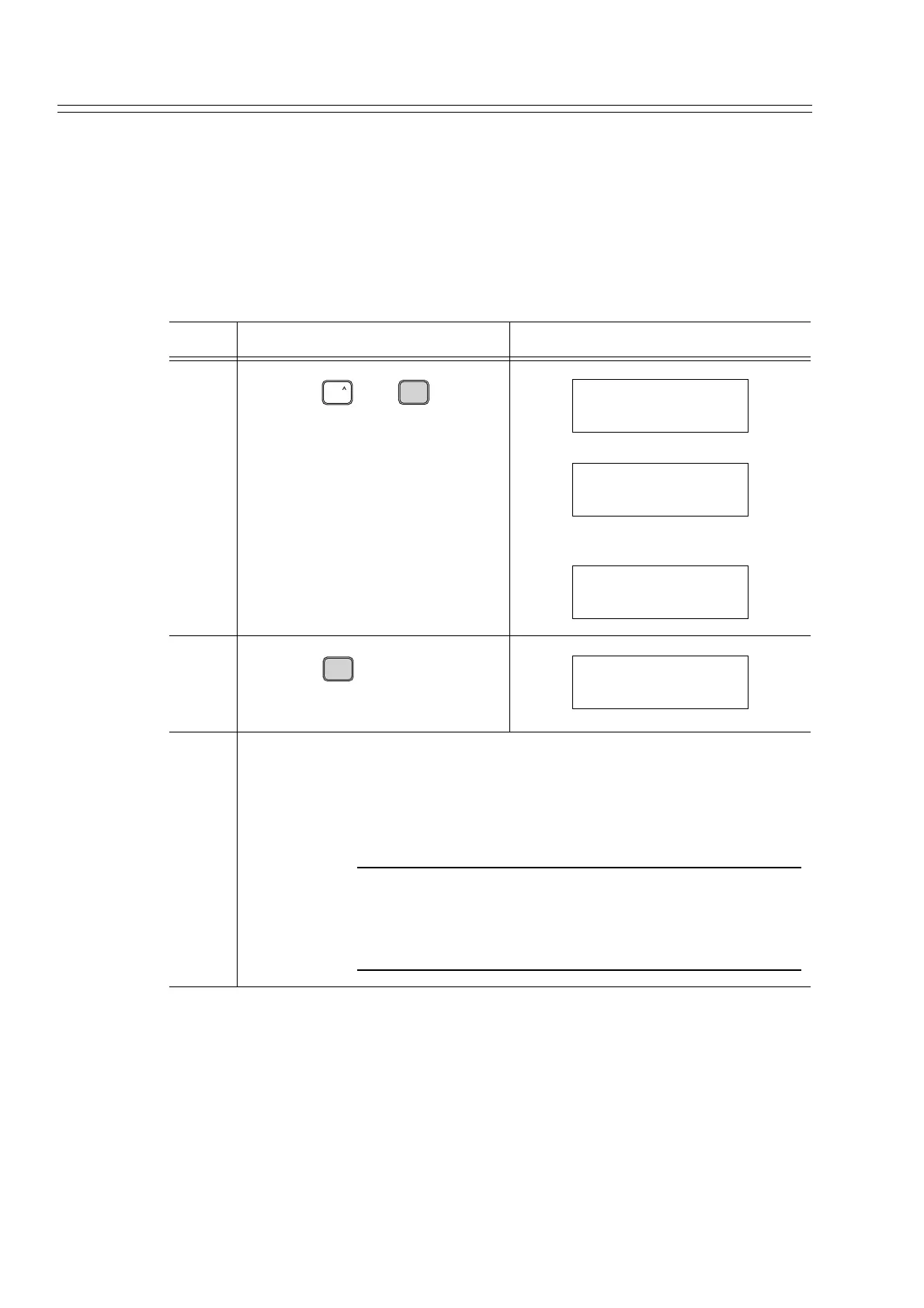
Step Description SFC screen
3
Press the and keys, in
that order
4
Press the key.
5 At the completion measurement, remove the clip from the communication
cable. Switch the process to normal operation
CAUTION
Securely close the cover of the transmitter case. Imperfect
closure allows entry of water, and may damage internal ter-
minals as well as the electronics module. Such damage may
require parts replacement, possibly of the entire module.
SHIFT
OUT-
J
PUT
INPUT
SHIFT-
INPUT FIT-1234
WORKING...
INPUT FIT-1234
25.00 kPa
OUT-
J
PUT
INPUT
OUTPUT FIT-1234
50.00 %