ENGINE
TNV IDI Service Manual
6-29
Cylinder Head
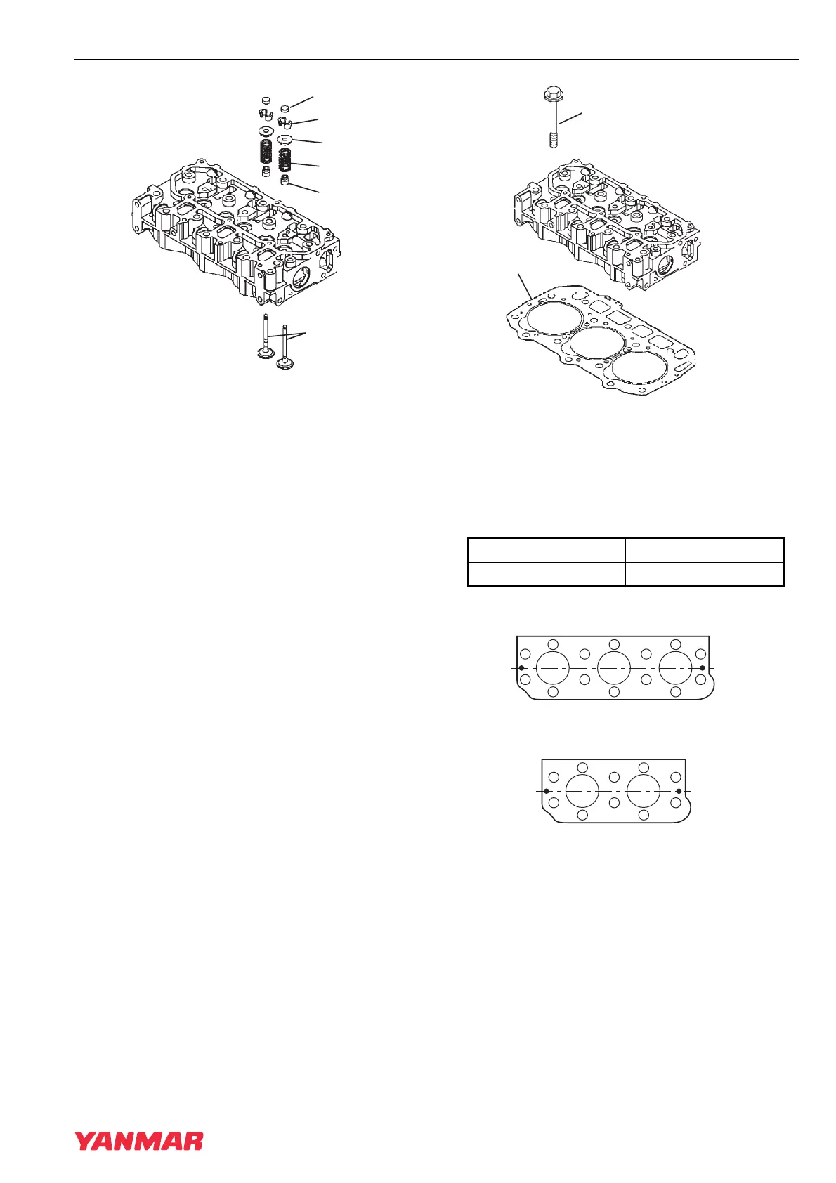
Figure 6-28
5. Put the cylinder head on the workbench with
the combustion side down to install the valve
springs. Reinstall the valve spring
(Figure 6-28, (4)) and spring retainer
(Figure 6-28, (5)).
6. Using a valve spring compressor tool,
compress the valve spring.
7. Insert the valve keeper (Figure 6-28, (2)) and
slowly release the tension in the valve spring.
Reinstall the valve cap (Figure 6-28, (1)).
Repeat steps on all remaining valves.
Reassembly of Cylinder Head
1. Carefully clean both the combustion surface of
the cylinder head and the top surface of the
cylinder block. Install a new cylinder head
gasket (Figure 6-29, (2)) on the cylinder block.
2. Position the cylinder head on the cylinder head
gasket.
Figure 6-29
3. Lightly oil the threads of the cylinder head bolts
(Figure 6-29, (1)). Tighten the bolts to the
specified torque shown in the chart below.
Tighten in the sequence shown in Figure 6-30.
See Torque for Bolts and Nuts on page 6-13.
1 –Cooling Fan End
2 –Camshaft Side
Figure 6-30
(1)
(2)
(3)
(4)
(5)
(6)
0002151
First Step 1/2 of final torque
Second Step Final torque
(1)
(2)
0002149
3
5
9
7
6
4
2
1
8
10
(1)
(2)
7
9
11
13
1
2
5
3
10
8
4
6
14
12
TNV_IDI_ServiceManual_A4.book 29 ページ 2012年2月24日 金曜日 午前10時24分
 Loading...