ENGINE
6-30
TNV IDI Service Manual
Cylinder Head
4. Insert the push rods in their respective
positions.
Reassembly of Rocker Arm Assembly
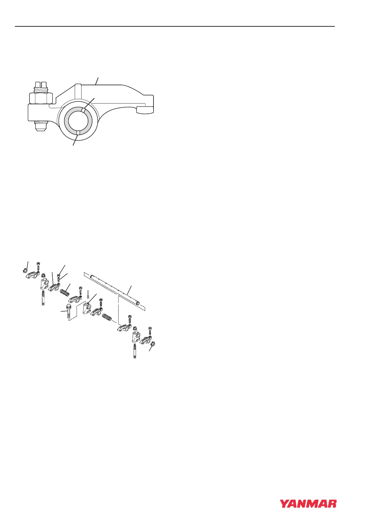
Figure 6-31
IMPORTANT
Ensure the lubrication holes in the rocker
arm shaft (Figure 6-31, (1)). are oriented
correctly with respect to the rocker arms
(Figure 6-31, (2)).
1. Lubricate the rocker arm shaft. Slide the rocker
arm supports (Figure 6-32, (5)), springs
(Figure 6-32, (4)) and rocker arms
(Figure 6-32, (1)) onto the shaft.
Figure 6-32
Note: The rocker arm shaft fits tightly in the
rocker arm supports. Clamp the support
in a padded vise. Twist and push on the
rocker arm shaft to reinstall.
Note: On 3-cylinder models, the set screw is
located in the center support. On
2-cylinder models, the set screw is
located in the front (cooling fan) end
support.
2. Align the hole in the rocker arm shaft
(Figure 6-32, (7)) and the hole in the rocker
arm support (Figure 6-32, (5)). Reinstall the
alignment set screw (Figure 6-32, (6)).
3. Place the rocker arm shaft assembly onto the
cylinder head.
4. If removed, reinstall the valve adjusting screws
(Figure 6-32, (3)) and lock nuts
(Figure 6-32, (2)).
5. Align the push rods with their respective rocker
arms.
6. Reinstall and tighten the rocker arm shaft
retaining bolts to the specified torque.
7. Tighten the rocker arm shaft alignment screw.
8. Adjust the valve clearance. See Measuring and
Adjusting Valve Clearance on page 6-32.
(2)
(1)
(1)
0001914
0002160
(7)
(8)
(6)
(9)
(1)
(8)
(5)
(4)
(3)
(2)
TNV_IDI_ServiceManual_A4.book 30 ページ 2012年2月24日 金曜日 午前10時24分
 Loading...