EasyManua.ls Logo

Yanmar CANplus 600 User Manual

Yanmar CANplus 600
40 pages
To Next Page IconTo Next Page
Page #1 background imageLoading...
Page #1 background image
Yanmar
®
600 Control Panel
Operation and Troubleshooting
463-3000-09 Initial - 16-May-2008 1
CANplus and CANplus logo are registered trademarks of LOFA Industries, Inc.
CP600 is a trademarks of LOFA Industries, Inc.
Introduction
The Yanmar CANplus
®
600 (CP600) control panel is an
economical platform to monitor and control electronically
governed diesel engines. Graphical gauge pages or a single
large analog gauge are displayed on the 4.25” diagonal
LCD. Virtually any SAE J1939 parameter reported by the
ECU (Engine Control Unit) can be displayed including RPM,
coolant temperature, oil pressure, engine hours, voltage and
diagnostic codes. The trans-reflective, backlit display is
clearly readable in both bright sunlight as well as total
darkness and is housed in a rugged IP67 rated housing.
Current alarm conditions are displayed in plain language on
popup messages and can be viewed in the alarm list.
Various diagnostic screens allow detailed investigation of the
CANbus data stream. By accessing the Configuration Menu,
users can customize displayed data to show metric or US
units, display language and various other parameters such
as the full-scale reading of gauges.
Five buttons access a context dependent button bar when
any button from 1 to 4 is pressed. The graphical menu
structure uses easily understood icons to indicate the
button’s current function. After 5 seconds of inactivity the
button bar disappears.
Button 1
Button 2 Button 3 Button 4 Button 5
Analog Gauge
Pages
Repeated presses
cycle through four
pages of analog
gauges (16 total).
Digital Gauge
Pages
Repeated presses
cycle through four
pages of digital
gauges (16 total).
Single Analog
Gauge
Repeated presses
cycle through
available analog
gauges.
Active Alarm
Page
Displays active
alarms including a
plain language
description.
Gauge
Adjust
Configures the
parameters
displayed by gauge
pages.
Question and Answer IconNeed help?

Do you have a question about the Yanmar CANplus 600 and is the answer not in the manual?

Yanmar CANplus 600 Specifications

General IconGeneral
ManufacturerYanmar
TypeControl Panel
DisplayLCD
Communication InterfaceCANbus
Communication ProtocolCAN

Summary

Introduction and Panel Overview

Introduction to CANplus 600

Describes the control panel's purpose, display, and customization features.

Button Functions Overview

Explains the context-dependent button bar and its functions accessed via buttons 1-4.

Operation and Maintenance Procedures

Throttle Control Options

Describes standard and alternative throttle control methods.

Service Timers

Explains the sixteen service timers for maintenance alerts.

Harness and Connector Details

Details on sealed and unsealed connectors and harness routing for proper installation.

Battery Circuit Requirements

Guidelines for proper battery connection, voltage, and protection.

Voltage Transient Suppression

Methods for suppressing voltage spikes in electrical circuits using diodes.

Welding Procedures

Safety procedures for welding on equipment with electronic controls.

Display Modes and Features

Analog Gauge Pages

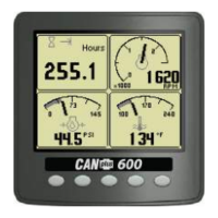
Details the four pages of analog gauges and how to configure them.

Digital Gauge Pages

Explains the digital display format for engine parameters.

Single Analog Gauge

Covers the mode for displaying a single large analog gauge and selectable gauge.

Active Alarms and Alarm List

Describes how active alarms are displayed and managed.

Adjusting Lighting and Contrast

How to adjust display brightness and contrast for readability.

Configuration and Settings

Configuration Menu

User interface for setting operational parameters like units and service timers.

Display Menu Configuration

Allows configuration of display items like units, language, and beep settings.

Gauges Menu Configuration

User configuration for gauge settings like Max RPM and Max Speed.

System Menu Configuration

Configuration for system functions like demo modes and restoring defaults.

J1939 Settings

Adjustments specific to the J1939 data link, including engine source and alarm filter.

PIN Settings and Security

Configuration for PIN security to access settings and PIN changes.

About Display Information

Displays product information like software version and part number.

Throttling Menu Configuration

Configuration for engine throttle control settings like Idle, Intermediate, and Run RPM.

Telemetry Menu Configuration

Configuration for the optional telemetry system, including addresses and status.

Db Viewer

Diagnostic tool to display and decode monitored data not normally shown.

Troubleshooting and Diagnostics

General Troubleshooting Guide

Common troubleshooting steps for engine and control system issues.

Engine Troubleshooting

Detailed troubleshooting for ECU power, fuel, and starting problems.

Control System Troubleshooting

Troubleshooting for self-test failures, data display issues, and ECU communication.

CANbus Testing Procedure

Procedure to test CANbus integrity and identify termination or connection issues.

Diagnostic Trouble Codes (DTC)

Explains SPN and FMI codes used for identifying specific faults.

Data Parameters Monitored

Lists all engine and transmission parameters available via CANbus for display.

Glossary of Terms

Defines technical terms and abbreviations used throughout the manual.