Installation 2-6
Drive Diagnostics Web Page
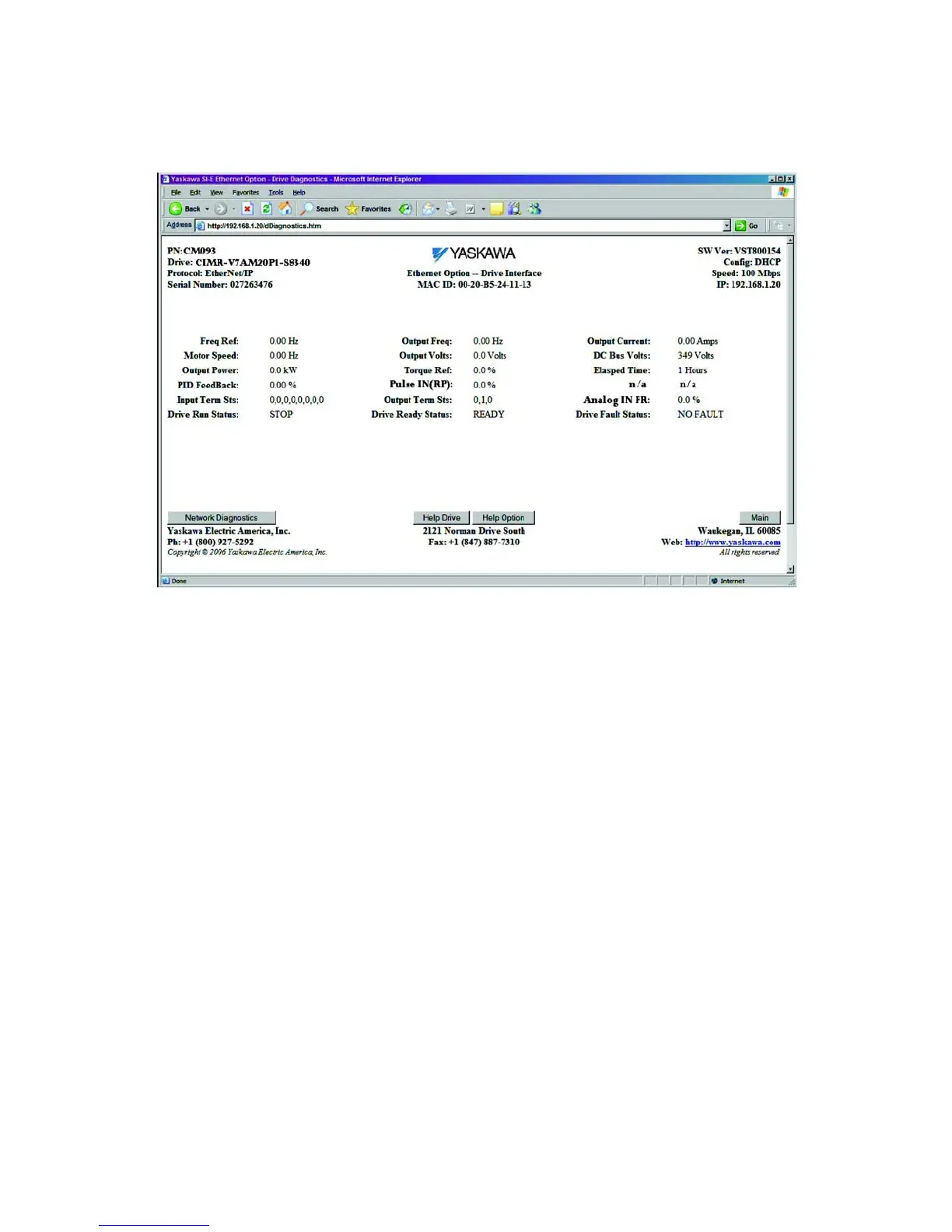
The drive diagnostics page contains the standard header and footer along with diagnostic information specific to the current drive.
Fig 2.5 – Drive Diagnostics Web Page
1. Freq Ref: Frequency Reference – Monitor Parameter U-01.
2. Motor Speed: Motor Speed – Monitor Parameter U-02.
3. Output Power: Output Power – Monitor Parameter U-11.
4. PID Feedback: PID Feedback in %. U-16.
5. Input Term Sts: The Digital Input status as bit field – Monitor Parameter U-06.
6. Drive Run Status: Indicates RUN/STOP state of the drive.
7. Output Freq: Output Frequency – Monitor Parameter U-02.
8. Output Volts: Output Voltage – Monitor Parameter U-04.
9. Torque Ref: Torque Reference in % of rated torque – Monitor Parameter U-08.
10. Pulse In (RP): Pulse Input (terminals RP to FC).
11. Output Term Sts: Digital Output status as bit field – Monitor Parameter U-07.
12. Drive Ready Status: Indicates the drive READY status.
13. Output Current: Output Current – Monitor Parameter U-03.
14. DC Bus Volts: DC bus Voltage – Monitor Parameter U-05.
15. Elapsed Time: Elapsed Time.
16. N/A:
17. Analog In FR: Analog input (terminals FR to FC).
18. Drive Fault Status: Indicates drive FAULT status.

 Loading...


