22
Read Multiple Registers Normal Response Message
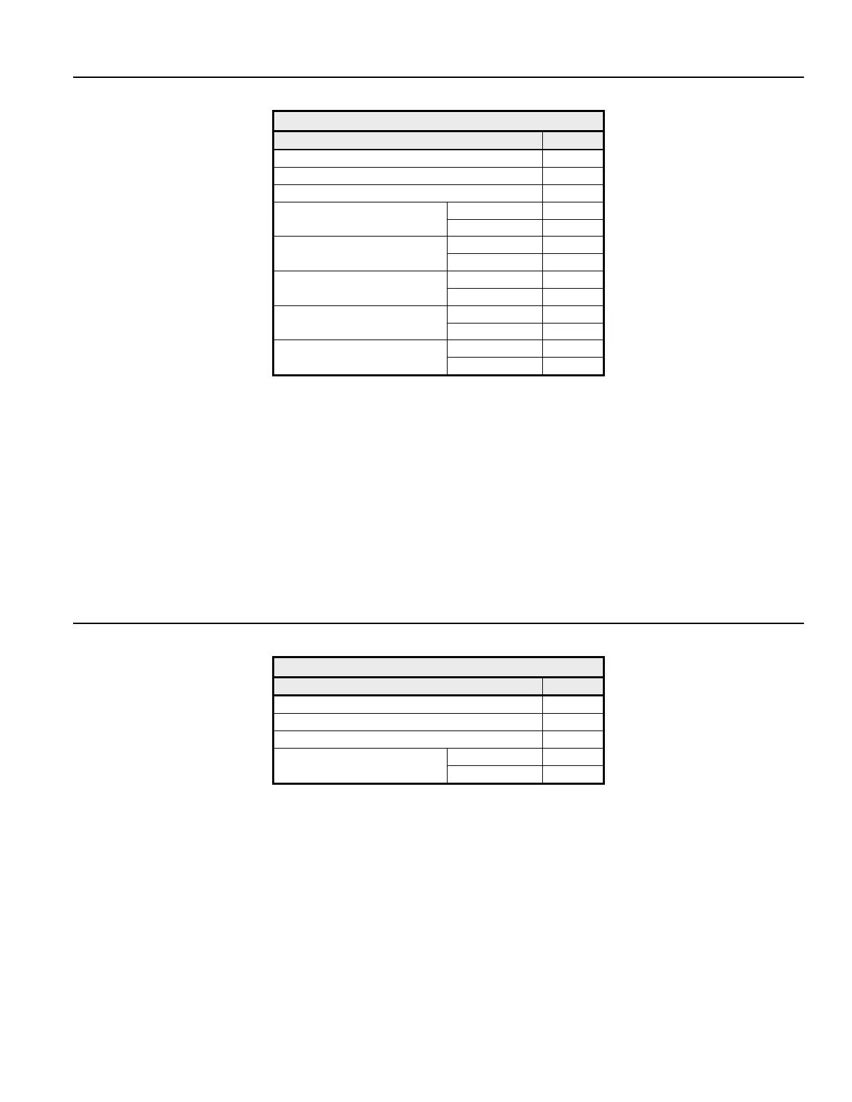
Table 2.3 Read Normal Response Message
Description Data
Slave Address 02h
Function Code 03h
Number of Data Bytes 08h
Upper 17h
Starting Register
Lower 70h
Upper 17h
Next Register
Lower 70h
Upper 01h
Next Register
Lower 09h
Upper 00h
Last Register
Lower 00h
Upper 38h
CRC-16
Lower ACh
The normal response message contains the same slave address and function code as the command message, indicating to the master which
specific slave is responding and to what type of function it is responding.
The number of data bytes is the number of data bytes returned in the response message. The number of data bytes is actually the number of
registers read times 2, since there are two bytes of data in each register.
The starting register is the address of the first register read.
The data section of the response message contains the data for the registers' requested read, in this case registers 20h, 21h, 22h and 23h. Their
data is 20h = 1770h, 21h = 1770h, 22h = 0109h and 23h = 0h.
Read Multiple Registers Fault Response Message
Table 2.4 Read Fault Response Message
Description Data
Slave Address 02h
Function Code 83h
Error Code 02h
Upper 30h
CRC-16
Lower
F1h
The fault response message contains the same slave address as the command message, indicating to the master, which slave is responding.
The function code of a fault response message is the logical OR of 80h and the original function code of 03h. This indicates to the master that
the message is a fault response message, instead of a normal response message.
The error code indicates where the error occurred in the command message. The value of 02h in the error code field of this fault response
message indicates that the command message requested data be read from an invalid register. Refer to section Error Codes, Table 2-14, for
more information on returned error codes.