27
Write Multiple Registers – Function Code 10H
The Write Multiple Register function allows the writing of data to from 1 to 16 consecutive registers.
Write Multiple Registers Command Message
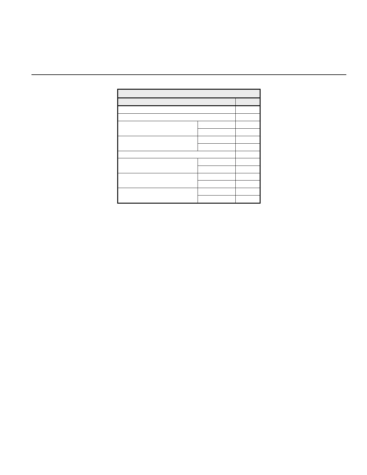
Table 2.11 Write Command Message
Description Data
Slave Address 01h
Function Code 10h
Upper 00h
Starting Register
Lower 01h
Upper 00h
Quantity
Lower 02h
Number of Data Bytes 04h
Upper 00h
First Register Data
Lower 01h
Upper 02h
Next Register Data
Lower 58h
Upper 63h
CRC-16
Lower 39h
Each G7 drive slave address is set via parameter H5-01. Valid slave addresses must be in the range of 1 ~ 20 hex (1 ~ 32 dec) and entered as a
hexadecimal number. No two slaves may have the same address. The master addresses the slave by placing the slave address in the Slave
Address field of the message. In the command message above, the slave is addressed at 01h. Broadcast address 0 is valid for register write
commands.
By setting the slave address to zero (0) in the command message, the master can send a message to all the slaves on the network simultaneously.
This is called simultaneous broadcasting. In a simultaneous broadcast message there is no response message.
The function code of this message is 10h (write multiple registers).
The starting register is the address of the first register to be written. In the command message above the starting register address is 01h (0001h).
The quantity indicates how many consecutive registers are to be written. The quantity may range from 1 to 16 registers. If an invalid quantity is
entered, error code of 03h is returned in a fault response message. In this command message there are two consecutive registers to be written:
0001h (Operation Command) and 0002h (Frequency Reference).
The number of data bytes is the number of bytes of data to be written. The number of data bytes is actually the quantity multiplied by 2, since
there are two bytes of data in each register.
The Data section contains the data for each register to be written in the order in which they are to be written.
A CRC-16 value is generated from a calculation including the message slave address, function code, starting register, quantity, Number of Data
Bytes, and all register data. The procedure for calculating a CRC-16 is described at the end of this chapter. When the slave receives the
command message it calculates a CRC-16 value and compares it to the CRC-16 of the command message. If the two CRC-16 values are
identical and the slave address is correct, the slave processes the command message. If the two CRC-16 values are not identical, the slave will
discard the command message and not respond.
If the command message has a valid slave address, function code, starting register, quantity, number of data bytes and data, and the slave will
respond with a normal response message. If the command message has an invalid function code, starting register, quantity, Number of Data
Bytes and/or data, the slave will respond with a fault response message. If the command message has an invalid slave address or CRC-16, no
response will be returned.