75
Modbus TCP/IP Specific Registers
(Only for use with the CM090 Modbus TCP/IP option card)
The Modbus TCP/IP Option Card CM090 differs slightly from Modbus RTU in its register structure. The CM090 card has a different
set of Command registers and additional monitor registers. However, all Monitor and Parameter registers listed earlier in this chapter
can also be accessed over Modbus TCP/IP. Other Modbus TCP/IP protocol specific items include:
A maximum of 10 simultaneous connections are allowed.
The Run Command and Frequency Reference may only be accessed through UNIT ID 1. While the drive is in remote RUN mode, the
Run command must be continually refreshed within the Timeout setting in the configuration webpage. This can be set from 100 ms to
30 sec. If the Run command is not refreshed within the set time, an EF0 fault will occur. Refer to the appropriate drive manual for
information on EF0 and setting the appropriate drive response. If a UNIT ID 1 connection is active, the NS/CON LED will blink at
approximately a 500 ms cycle.
The TCP/IP connection must be refreshed within 60 seconds. If it is not refreshed within 60 seconds, the connection will be closed.
This implementation of Modbus TCP/IP supports Modbus functions 3 (read multiple registers), 6 (write single register) and 16 (write
multiple registers).
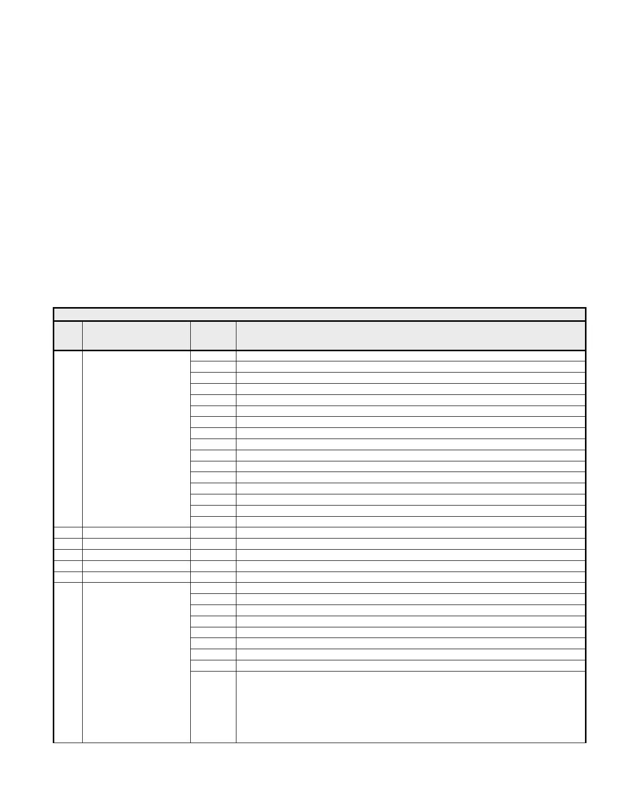
Table 4.15 Modbus TCP/IP Interface Registers
Addr.
Function Bit Description
0h Forward Run Input
1h Reverse Run Input
2h Multi-Function Digital Input Terminal S3. Function set by setting of H1-01
3h Multi-Function Digital Input Terminal S4. Function set by setting of H1-02
4h Multi-Function Digital Input Terminal S5. Function set by setting of H1-03
5h Multi-Function Digital Input Terminal S6. Function set by setting of H1-04
6h Multi-Function Digital Input Terminal S7. Function set by setting of H1-05
7h Multi-Function Digital Input Terminal S8. Function set by setting of H1-06
8h External Fault Input (EF0)
9h Fault Reset
Ah Multi-Function Digital Input S9. Function set by setting of H1-07
Bh Multi-Function Digital Input S10. Function set by setting of H1-08
Ch Multi-Function Digital Input S11. Function set by setting of H1-09
Dh Multi-Function Digital Input S12. Function set by setting of H1-10
Eh Fault Trace (U2 and U3 Monitors) Clear Input
0001h
Command
Fh External Base Block Input
0002h
Frequency Reference - Dependent on setting of o1-03
0003h
Torque Reference - Units 0.1%
0004h
Torque Compensation - Units 0.1%
0007h
Terminal FM - Sets the value of analog output terminal FM. (-1540 / -11VDC ~ 1540 / +11VDC)
0008h
Terminal AM - Sets the value of analog output terminal AM. (-1540 / -11VDC ~ 1540 / +11VDC)
0h Multi-Function Digital Output 1 (M1-M2)
1h Multi-Function Digital Output 2 (M3-M4)
2h Multi-Function Digital Output 3 (M5-M6)
3h Multi-Function Digital Output 4 (P3-C3)
4h Multi-Function Digital Output 5 (P4-C4)
5h Reserved
6h Fault Contact Output Enable (1 = Enable bit 7)
7h Fault Contact Digital Output (MA, MB, MC)
0009h
Digital Output
8h-Fh
Reserved