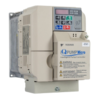
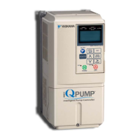
YASKAWA TOEP YAIQPM 01A iQpump Micro Quick Start Procedure
iQpump Micro
Quick Start Procedure
Page 6
of 31
Motor, Line Power and Start/Stop Circuit
4
STEP
4.1 Remove the front cover
NOTICE: Improper removal of the the drive’s protective covers and conduit bracket (NEMA
1, UL Type 1) can cause damage to the drive. Adhere to iQpump User Manual, Section 3,
Protective Covers to avoid drive damage.
4.2 Connect main input power and motor wiring to the drive.
Refer to Figure 1 for single-phase input power drive models.
Refer to Figure 2 for three-phase input power drive models.
Follow accepted wiring practices and applicable electric codes. Ensure all equipment is properly
grounded.
WARNING! Fire Hazard. Do not connect terminals B1, B2 (-), +1, +2
terminals to earth ground. Only connect ground wiring to designated
ground terminals.
U/T1 V/T2 W/T3
1Ø Line
Input Power
Connect
frame to
ground
Input
Protection
(Fuse or C.B.)
Exchange any two
of the three motor
leads to change
motor rotation
direction.
L1
L2
Connect to chassis
ground
(S/L2)(R/L1)
(U/T1) (V/T2) (W/T3)
Sizing note: Verify the drive is properly sized for single phase input
power. The drive input line voltage must be equal to or greater than motor
rated voltage for best performance.
Figure 1: Line and Motor Electrical
Connections - Single-Phase Input Power
R/L1 S/L2
Drive
Power
Terminals
Single-phase
Input Line Power
Output Motor
3Ø
Induction
motor
U/T1 V/T2 W/T3
3Ø Line
Input Power
L1
L2
L3
R/L1 S/L2
T/L3
(U/T1) (V/T2) (W/T3)
Connect
frame to
ground
Input
Protection
(Fuse or C.B.)
Connect to chassis
ground
(R/L1) (S/L2) (T/L3)
Exchange any two
of the three motor
leads to change
motor rotation
direction.
Figure 2: Line and Motor Electrical
Connections - Three-Phase Input Power
Drive
Power
Terminals
Three-phase
Input Line Power
Output Motor
3Ø
Induction
motor
4.3 Select start / stop control method, (parameter b1-02). Remove the drive terminal cover to access
the control terminals. The drive will START and STOP from the keypad from the factory. If this is the preferred start/stop method
then continue to the feedback signal connection section. Refer to the wiring diagram below to START/STOP the drive using an
external switch or contact 2-Wire Start/Stop Wiring Diagram
S3 S5 S6 S7 HC SC H1 RPS2 S4S1
Forward
Run
Use for maintained contacts
2-Wire Control
iQpump Micro Terminals TB1-1
NEMA 1, UL Type 1 Enclosure
-
+1 +2B1 B2

 Loading...


