3 Electrical Installation
YASKAWA Europe TOEP C710616 92D AC Drive L1000H Quick Start Guide 10
3 Electrical Installation
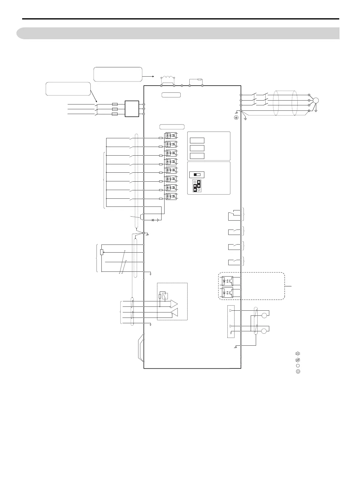
The figure below shows the main and control circuit wiring.
Note: 1. The drive should be implemented in the system in a way so that a drive fault causes the safety chain to open. Always use terminal
MA-MB-MC for this purpose.
2. Even though no fault is present, conditions where the drive may not start can occur, e.g. when the Digital Operator is left in the
Programming Mode. Use the “Drive Ready” output (default set to terminals M5-M6) to interlock operation in such situations.
<1> Remove the jumper when installing a DC reactor. Models 40045 through 40150 come with a built-in DC reactor.
<2> The drive provides a stop function in compliance with Stop Category 0 (EN 60204-1) and “Safe Torque Off” (IEC/EN 61800-5-2). It has been
designed to meet the requirements of the ISO/EN 13849-1, Category 3 PLd, and IEC/EN 61508, SIL2 (Models CIMR-LA) or SIL3
(Models CIMR-LF). Using this function the number of motor contactors can be reduced to one. Refer to Safe Disable Input Function on
page 42 for details.
<3> Never short terminals SP and SN, as doing so will damage the drive.
<4> Disconnect the wire jumper between H1-HC and H2-HC when utilizing the Safe Disable inputs.
CN5-C
CN5-B
CN5-A
Option card connectors
Off
On
P1
P2
C1
C2
Photo Coupler 1
(Safe disable status)
Photo Coupler 2
(Speed Agree)
Digital output
5 to 48 Vdc
2 to 50 mA
(default setting)
+
−
+
+
++
M
U/T
1
V/T2
W/T
U
V
W
3
Ground
Terminals -, +1, +2, B1, B2 are
for connecting options. Never
connect power supply lines to
these terminals
DC reactor
(option)
UX
Braking resistor
(option)
+
−
+
+
++
+
−
UX
S
1
S2
S3
S4
S5
S6
S7
DM
DM
A
1
A2
0
V
AC
R
R
S
S
IG
H
1
H2
HC
Drive
B112
B2
2
kΩ
S8
SC
0 V
FM
AM
AC
E (G)
<1>
−
+24 V
+V
MA
M
1
M2
MB
MC
Jumper
Braking resistor
(option)
Up command / Stop
Not Used
Nominal Speed
Intermediate Speed
Not Used
Multi-function
digtial inputs
(default setting)
Sink / Source mode
selection wire link
(default: Sink)
Shield ground terminal
Multi-function
analog inputs
Power supply +10.5 Vdc, max. 20 mA
Analog Input 1 (Oil temperature)
-10 to +10 Vdc (20 k
Ω
)
Analog Input 2 (Not used)
-10 to +10 Vdc (20 k
Ω
)
−V
Power supply, -10.5 Vdc, max. 20 mA
MEMOBUS/Modbus
comm. RS485/422
max. 115.2 kBps
Termination resistor
(120
Ω
, 1/2 W)
DIP
Switch S2
Fault relay output
250 Vac, max. 1 A
30 Vdc, max 1 A
(min. 5 Vdc, 10 mA)
Multi-function relay output (Safe disable status)
250 Vac, max. 1 A
30 Vdc, max 1 A
(min. 5 Vdc, 10 mA)
Multi-function analog output 1
(Output Speed)
-10 to +10 Vdc (2mA)
Multi-function analog output 2
(Output Current)
-10 to +10 Vdc (2mA)
EDM (Safety Electronic Device Monitor)
Main Circuit
Control Circuit
shielded line
twisted-pair shielded line
main circuit terminal
control circuit terminal
R/L1
S/L2
T/L3
Motor
Shielded
Cable
M3
M4
Multi-function relay output (not used)
M5
M6
Multi-function relay output (not used)
SP
SN
DIP Switch S2
Term. Res. On/Off
Jumper S3
H1, H2
Sink/Source Sel.
Terminal board
jumper and switch
FM
+
−
AM
<3>
Down command / Stop
Inspection Speed
Not Used
<2>
<4>
Safe Disable inputs
Fuse
EMC
Filter
MCMC
2MCCB2MCCB
MBMB
ONON
OFFOFF
THRXTHRX
SASA
1
2
TRX
TRX
MCMC
MAMA
TRXTRX
Fault relayFault relay
contactcontact
Braking resistor unitBraking resistor unit
Thermal relay trip contactThermal relay trip contact
MCMC
MCMC
SASA
SASA
THRXTHRX
ELCB (MCCB)
R
T
S
Three-phase
power supply
200 to 240 V
50/60 Hz
2MCCB2MCCB
r1r1
s1s1
t1t1
MC
Wiring sequence should shut off
power to the drive when a fault
output is triggered.
If running from a 400 V power If running from a 400 V power
supply, a step-down transformer supply, a step-down transformer
is needed to reduce the voltage is needed to reduce the voltage
to 200 V.to 200 V.

 Loading...


