5 Installation Procedure
16 YASKAWA ELECTRIC SIEP C730600 70B V1000 Option SI-EP3/V Technical Manual
Table 7 Ground Wire Selection
5. For IP20/Open-Chassis models, go to Step 17. on page 21.
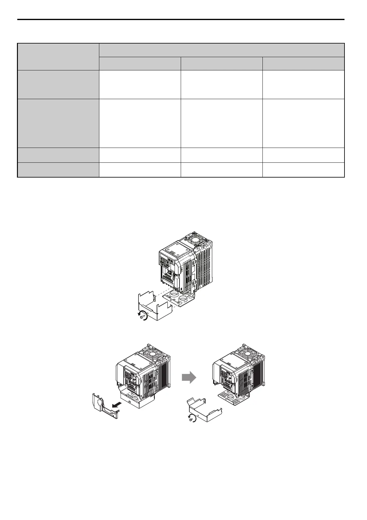
6. For IP20/UL Type 1 enclosure models CIMR-VAF, loosen the screw on the front of the terminal
cover and remove it from the drive. Refer to Figure 9 for details.
Refer to Figure 10 for drive models CIMR-VBA0006F to BA0018F, 2A0010F to 2A0069F, and 4A0001F to
4A0038F, which require removing the plastic terminal cover prior to removing the terminal cover.
Note: Installing the option on an IP20/UL Type 1 enclosure drive voids UL Type 1 protection while maintaining IP20 conformity.
Figure 9
Figure 9 Remove the UL Type 1 Terminal Cover
(CIMR-VBA0001F to BA0003F, 2A0001F to 2A0006F)
Figure 10
Figure 10 Remove the Terminal Cover on an IP20/UL Type 1 Drive
(Models CIMR-VBA0006F to BA0018F; 2A0008F to 2A0069F; 4A0001F to 4A0038F)
Ground Wire Length
mm (in)
Drive Model
CIMR-V
Single-Phase
200 V Class
Three-Phase
200 V Class
Three-Phase
400 V Class
150 (5.9)
BA0001
BA0002
BA0003
2A0001
2A0002
2A0004
2A0006
–
200 (7.9)
BA0006
BA0010
BA0012
BA0018
2A0010
2A0012
2A0020
4A0001
4A0002
4A0004
4A0005
4A0007
4A0009
4A0011
250 (9.8)
–
2A0030
2A0040
4A0018
4A0023
400 (15.7)
–
2A0056
2A0069
4A0031
4A0038
PROFINET_E_conditional.fm 16 ページ 2016年6月20日 月曜日 午後8時2分