5 Installation Procedure
YASKAWA ELECTRIC SIEP C730600 70B V1000 Option SI-EP3/V Technical Manual 25
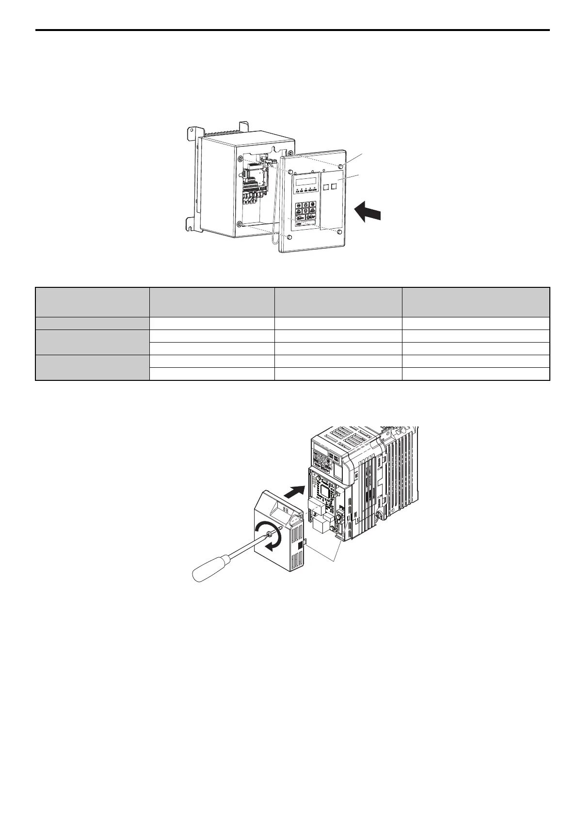
29. Reattach the front cover of the drive using four screws (see Figure 30). Refer to Table 9 on page 25 for
tightening torque specifications.
NOTICE: Damage to Equipment. Take proper precautions when wiring the option so that the front covers will easily fit back onto the
drive. Make sure no cables are pinched between the front covers and the drive when replacing the cover. Failure to comply may result
in damage to circuitry and equipment.
Figure 30
Figure 30 Attach the Front Cover
Table 9 IP66/UL Type 4X Front Cover Installation Screw Size and Tightening Torque
30. For IP66/UL Type 4X enclosure models, go to Step 32. on page 25.
31. For IP20/Open-Chassis or IP20/UL Type 1 enclosure models, attach the option cover by aligning the tabs with
the mounting holes, seat the front cover into place, and tighten the screw on the front.
Figure 31
Figure 31 Attach the Option Cover
Note: Take proper precautions when wiring the option so that the front covers will easily fit back onto the drive. Make sure no cables
are pinched between the front covers and the drive when replacing the covers.
32. Set drive parameters in Table 10 for proper option performance.
Voltage Class Model No. CIMR-V
Installation
Screw Size
Tightening Torque
Nm
(lb-in)
Single Phase 200 V Class BA0001 to BA0012 M5 2.0 to 2.5 (17.7 to 22.1)
Three Phase 200 V Class
2A0001 to 2A0020 M5 2.0 to 2.5 (17.7 to 22.1)
2A0030 to 2A0069 M6 5.4 to 6.0 (47.8 to 53)
Three Phase 400 V Class
4A0001 to 4A0011 M5 2.0 to 2.5 (17.7 to 22.1)
4A0018 to 4A0038 M6 5.4 to 6.0 (47.8 to 53)
Front cover
Front cover screw
PROFINET_E_conditional.fm 25 ページ 2016年6月20日 月曜日 午後8時2分