5.9 Adjustments
5.9 Adjustments
5.9.1 Servo System Adjustments
Once the load inertia constant (Cn-0003) has been specified, the following user constants (pa-
rameters) are used to adjust the servo system.
• Cn-0004: Speed Loop Gain
• Cn-0005: Speed Loop Integration Time Constant
• Cn-0017: Torque Reference Filter Time Constant
• Cn-001A: Position Loop Gain
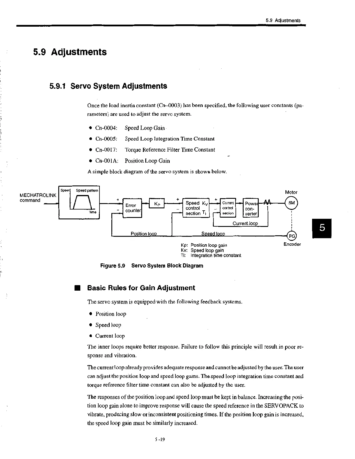
A simple block diagram of the servo system is shown below.
Spee
MECHATROLINK
command
Speed pattern
Time
••••••••••o
Error
counter
Kp
Position loop
Speed Kv
control
section Ti
.••••
Current
control
section
1111111• •
Powe
con-
verter
Current loop
Speed loop
Kp: Position loop gain
Kv: Speed loop gain
Ti: Integration time constant
Figure 5.9 Servo System Block Diagram
■ Basic Rules for Gain Adjustment
The servo system is equipped with the following feedback systems.
Motor
SM
(1.1)
Encoder
• Position loop
• Speed loop
• Current loop
The inner loops require better response. Failure to follow this principle will result in poor re-
sponse and vibration.
The current loop already provides adequate response and cannot be adjusted by the user. The user
can adjust the position loop and speed loop gains. The speed loop integration time constant and
torque reference filter time constant can also be adjusted by the user.
The responses of the position loop and speed loop must be kept in balance. Increasing the posi-
tion loop gain alone to improve response will cause the speed reference in the SERVOPACK to
vibrate, producing slow or inconsistent positioning times. If the position loop gain is increased,
the speed loop gain must be similarly increased.
5 -19
 Loading...


