9.1 AC Servomotors
1
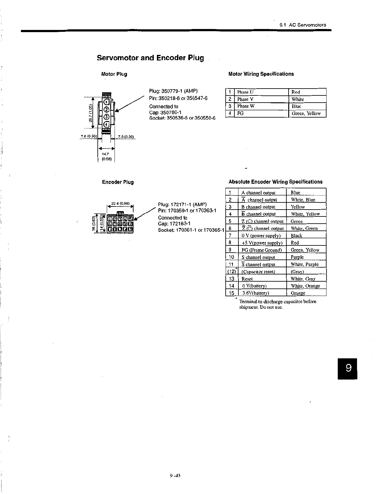
Phase U
Red
2
Phase V
White
3 Phase W
Blue
4 FG
Green, Yellow
1 A channel output Blue
2 A channel output
White, Blue
3 B channel output
Yellow
4
B channel output White, Yellow
5 Z (C) channel output Green
6 Z (C) channel output White, Green
7
0 V (power supply) Black
8 +5 V(power supply)
Red
9 FG (Frame Ground)
Green, Yellow
10
S channel output
Purple
11
S channel output White, Purple
*
(12) (Capacitor reset)
(Gray)
13
Reset
White, Gray
14
0 V(battery)
White, Orange
15 3.6V(battery)
Orange
Servomotor and Encoder Plug
Motor Plug
0
7.6 (0.30) U 7.6 0.30
Encoder Plug
•
.?
d
22.4 (0.88) .4
11
woorDs
ammo
610012E9
Plug: 350779-1 (AMP)
Pin: 350218-6 or 350547-6
Connected to
Cap: 350780-1
Socket: 350536-6 or 350550-6
Plug: 172171-1 (AMP)
Pin: 170359-1 or 170363-1
Connected to
Cap: 172163-1
Socket: 170361-1 or 170365-1
Motor Wiring Specifications
Absolute Encoder Wiring Specifications
Ter mi nal to discharge capacitor before
shipment. Do not use.
9
 Loading...


