4.4 Connecting an Incremental Encoder
• I/O Signal Connections and External Signal Processing
SERVOPACK
(SGDB-1=11=11=1N)
+24V 6 3.3k S2
Forward drive prohibited
Forward overtravel OFF
at overtravel.
) .71=—P
OV P-LS Approx. 7 mA
Reverse drive prohibited N-OT
( Reverse overtravel OFF ) N-LS 8
at overtravel.
— I. Forward drive prohibited
DEC
Zero point return deceleration LS 0
(ON when above LS) DEC-LS 9
External latch LS (signal) EXT
—0 0
(ON when latched)
EXT-LS 10
+24V ALM ALM
Alarm output
(OFF with alarm)
OV
Brake interlock output
(ON with servo ready)
E -7-r".(1-r14 ALM—SG 3
4
BRK BK
.-, '''T
m
- Reverse drive prohibited
Zero point return deceleration LS ON
- External latch signal ON
4-- Servo alarm
BK-SG 1
2
Brake interlock
26
FG
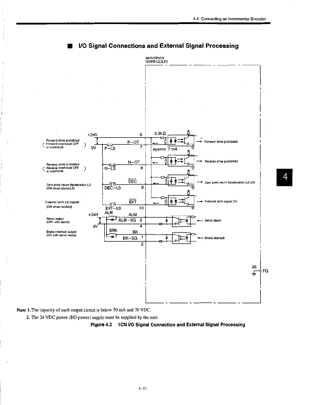
Note 1.The capacity of each output circuit is below 50 mA and 30 VDC.
2. The 24 VDC power (I/O power) supply must be supplied by the user.
Figure 4.2 1CN I/O Signal Connection and External Signal Processing
4-11
 Loading...


