4.9 4CN Connectors for MECHATROLINK Communications
SH 3
SH 8
FG 5
Pulse transformer
MECHATROLIN
I/F
Host controller
*S
S 2
P
6
7
S
*S 6
1200 R 4
J-
S 7
Note
•
S
Pulse transormer
4
R
21. S
1200
3
5
6
P 7
SH
SH
FG
f—MECHATROLINK I/F
r 1
No.1 SERVOPACK (First axis)
S
S
S
Pulse transformer
4
2
R
S
1200
SH
3
5
SH
FG
MECHATROLINK
I/F
No.2 SERVOPACK (Second axis)
P7
S
1
S
Pulse transformer
4
2
8
1200
S
SH
3
SH
5
FG
MECHATROLINK
I/F
SERVOPACK (Last axis)
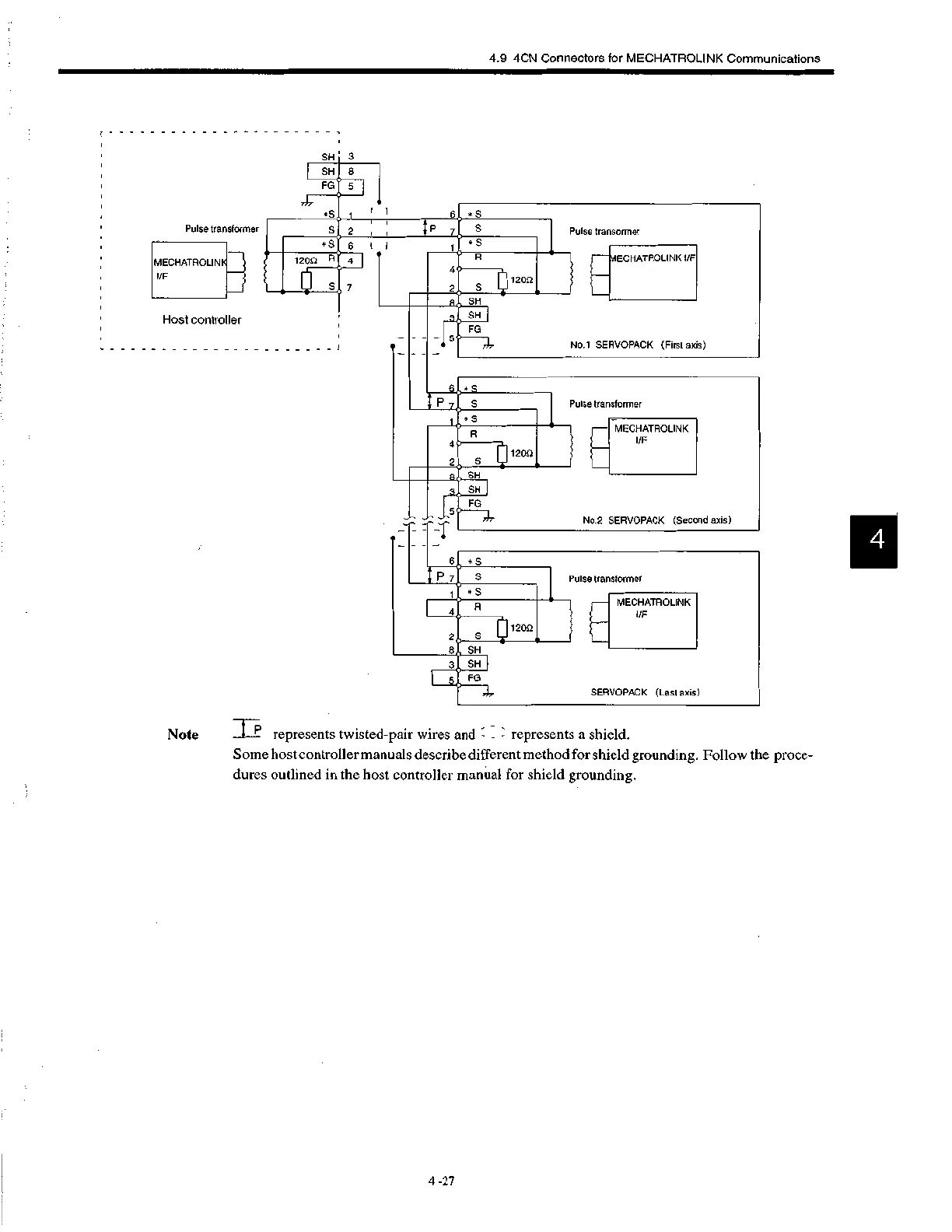
P , -
represents twisted-pair wires and - - - represents a shield.
Some host controller manuals describe different method for shield grounding. Follow the proce-
dures outlined in the host controller manual for shield grounding.
 Loading...


