5.2 Position Control
Load travel distance per load shaft revolution = 12/0.01 = 1200 (reference units)
Determining the Electronic Gear Ratio (B/A)
B = [(Cn-0011) x 4] x (motor shaft revolution speed)
A = [Load travel distance per load shaft revolution (reference units)] x (load shaft speed)
Reduce the electronic gear ratio (B/A) to the lowest terms so that both A and B are less than
32768, and then set A and B in Cn-0025 and Cn-0024.
II Motor Shaft and Load Shaft Revolution Speed
The motor shaft and load shaft speeds form the gear ratio for the mechanical system. If the me-
chanical system is structured so that load shaft makes "1" revolutions when the motor shaft makes
"m" revolutions, the gear ratio for the motor shaft and the load shaft is m/l, as shown below.
Motor shaft speed: m (revolutions)
Load shaft speed: 1 (revolutions)
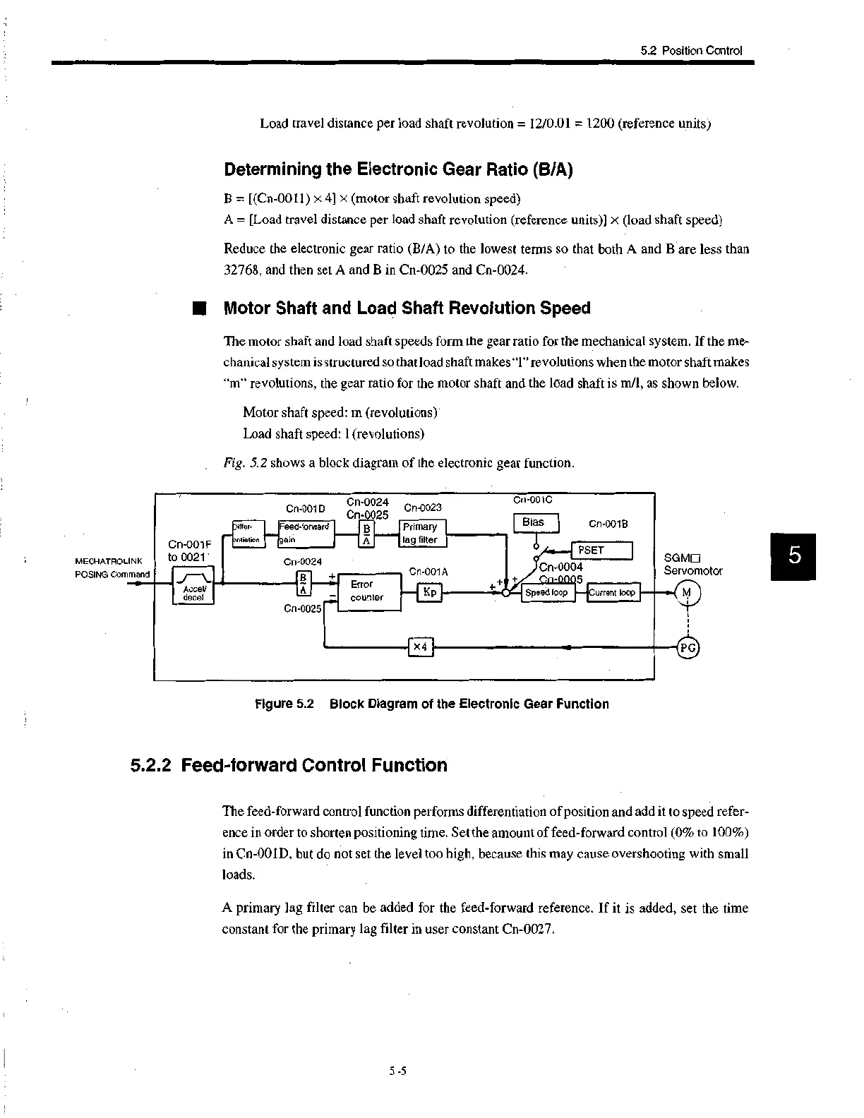
Fig. 5.2 shows a block diagram of the electronic gear function.
MECHATROLINK
POSING Command
Cn-001F
to 0021
Differ.
entiatlon
Cn-001D
Feed-forward
gain
Cn-0024 Cn-0023
Cn-0025
Accel/
decal
Cn-0024
Cn-0025
Primary
A lag filter
Error
counter
Cn-001A
K
++
Cn-001C
Bias
Cn-001B
PSET
Cn-0004
5
Speed loop —lCurrent loop
SG MEI
Servomotor
Figure 5.2 Block Diagram of the Electronic Gear Function
5.2.2 Feed-forward Control Function
The feed-forward control function performs differentiation of position and add it to speed refer-
ence in order to shorten positioning time. Set the amount of feed-forward control (0% to 100%)
in Cn-001D, but do not set the level too high, because this may cause overshooting with small
loads.
A primary lag filter can be added for the feed-forward reference. If it is added, set the time
constant for the primary lag filter in user constant Cn-0027.
5 -5
 Loading...


