5.6 Precautions
1MC
o R
o s
T
0®
o r
pt
1CN-
(PHC)
Three-phase AC
Uo
200 to 230 V
VO
Wa
5RY
2CN
r Servo
alarm
+24V
3
0 V
4
P1
SERVOPACK Model
Applicable Regenerative
Resistor Unit
Regenerative Resistor (SI)
SGDB-60AN
JUSP-RA04 6.25
SGDB-75AN
JUSP-RA05
3.13
SGDB-1AAN
SGDB-1 EAN
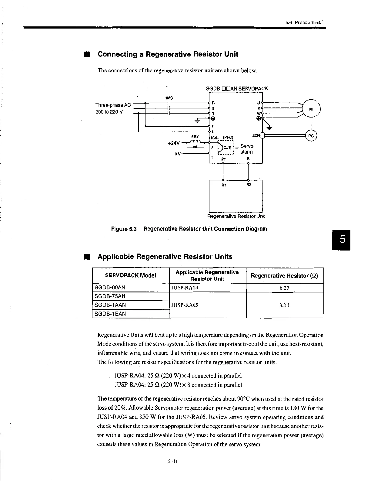
III Connecting a Regenerative Resistor Unit
The connections of the regenerative resistor unit are shown below.
SG DB-DOAN SERVOPACK
R1
R2
Regenerative Resistor Unit
Figure 5.3 Regenerative Resistor Unit Connection Diagram
II Applicable Regenerative Resistor Units
Regenerative Units will heat up to a high temperature depending on the Regeneration Operation
Mode conditions of the servo system. It is therefore important to cool the unit, use heat-resistant,
inflammable wire, and ensure that wiring does not come in contact with the unit.
The following are resistor specifications for the regenerative resistor units.
. JUSP-RA04: 25 f2 (220 W) x 4 connected in parallel
JUSP-RA04: 25 S2 (220 W) x 8 connected in parallel
The temperature of the regenerative resistor reaches about 90°C when used at the rated resistor
loss of 20%. Allowable Servomotor regeneration power (average) at this time is 180 W for the
JUSP-RA04 and 350 W for the JUSP-RA05. Review servo system operating conditions and
check whether the resistor is appropriate for the regenerative resistor unit because another resis-
tor with a large rated allowable loss (W) must be selected if the regeneration power (average)
exceeds these values in Regeneration Operation of the servo system.
5 -11
 Loading...


