5.7 Application Precautions
5.7 Application Precautions
5.7.1 Noise Control
III Example of Wiring for Noise. Control
This SERVOPACK uses high-speed switching elements in the main circuit. It may be subjected
to switching noise from these high-speed switching elements if wiring or grounding around the
SERVOPACK is not appropriate. To prevent this, always wire and ground the SERVOPACK
correctly.
The SERVOPACK also has a built-in microprocessor (CPU). Therefore install a noise filter to
protect the microprocessor from external noise.
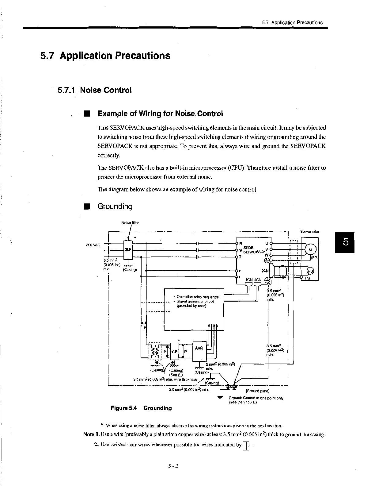
The diagram below shows an example of wiring for noise control.
• Grounding
200 VAC
P
Noise filter
1.
2LF
OR
SGDB
O S SERVOPACK
3.5 mm2
(0.005 in2)
min. (Casing)
• Operation relay sequence
__ • Signal generator circuit
(provided by user)
OT
U
O r 2CN
0 t
1CN 4CN
up
J
P 1LF
•
AVR
7777" 2 mm2 (0.003 In2)
(Casing (Casing) "" min.
(See 2.) (Casing) I
3.5 mm2 (0.005 in2) min. wire thickness „or 77/r7-
7" (Casing)
3.5 mm2 (0.005 In2) min.
Figure 5.4 Grounding
3.5 mm2
(0.005 in2)
min.
3.5 mm2
(0.005 in2)
min.
(Ground plate)
=• Ground: Ground to one point only
(less than 100 ft)
r--1
Servomotor
(FG
FG
* When using a noise filter, always observe the wiring instructions given in the next section.
Note 1. Use a wire (preferably a plain stitch copper wire) at least 3.5 mm2 (0.005 in2) thick to ground the casing.
2. Use twisted-pair wires whenever possible for wires indicated by IP
.
5 -13
 Loading...


