EasyManuals Logo

YASKAWA V1000 Replacing Guide

YASKAWA V1000
35 pages
To Next Page IconTo Next Page
To Previous Page IconTo Previous Page
Page #11 background imageLoading...
Page #11 background image
VAN-V19001E [V1000→GA500]
11/35
Analog Input
Name
Signal Level
V1000
GA500
V1000
GA500
H1
H1
Safe Disable input 1
24 VDC, 10 mA
maximum
ON (closed): Normal
operation
OFF (open): Coasting
Internal impedance 3.3
Minimum OFF width:
1ms or less
*5
*6
24 VDC, 6 mA
maximum
ON (closed): Normal
operation
OFF (open): Coasting
Internal impedance:
4.7kΩ
Minimum OFF width:
3ms or less
*7
H2
Safe Disable input 2
HC
HC
Safe Disable function common
Safe command common
Safe Disable function common
Note: Do not short-circuit the terminals HC and SN
MA
MA
N.O. output (error)
Relay output
30 VDC 10 mA to 1 A
250 VAC 10 mA to 1 A
MB
MB
N.C. output (error)
MC
MC
Digital output common
P1
P1
Multi-function PHC output 1
Note: Factory default function
V1000: During Run
GA500: During Run
Photocoupler output
48 V, 50 mA maximum
*9
Photocoupler output
48 V, 2 mA to 50 mA
*9
C1
*8
P2
P2
Multi-function PHC output 2
Note: Factory default function
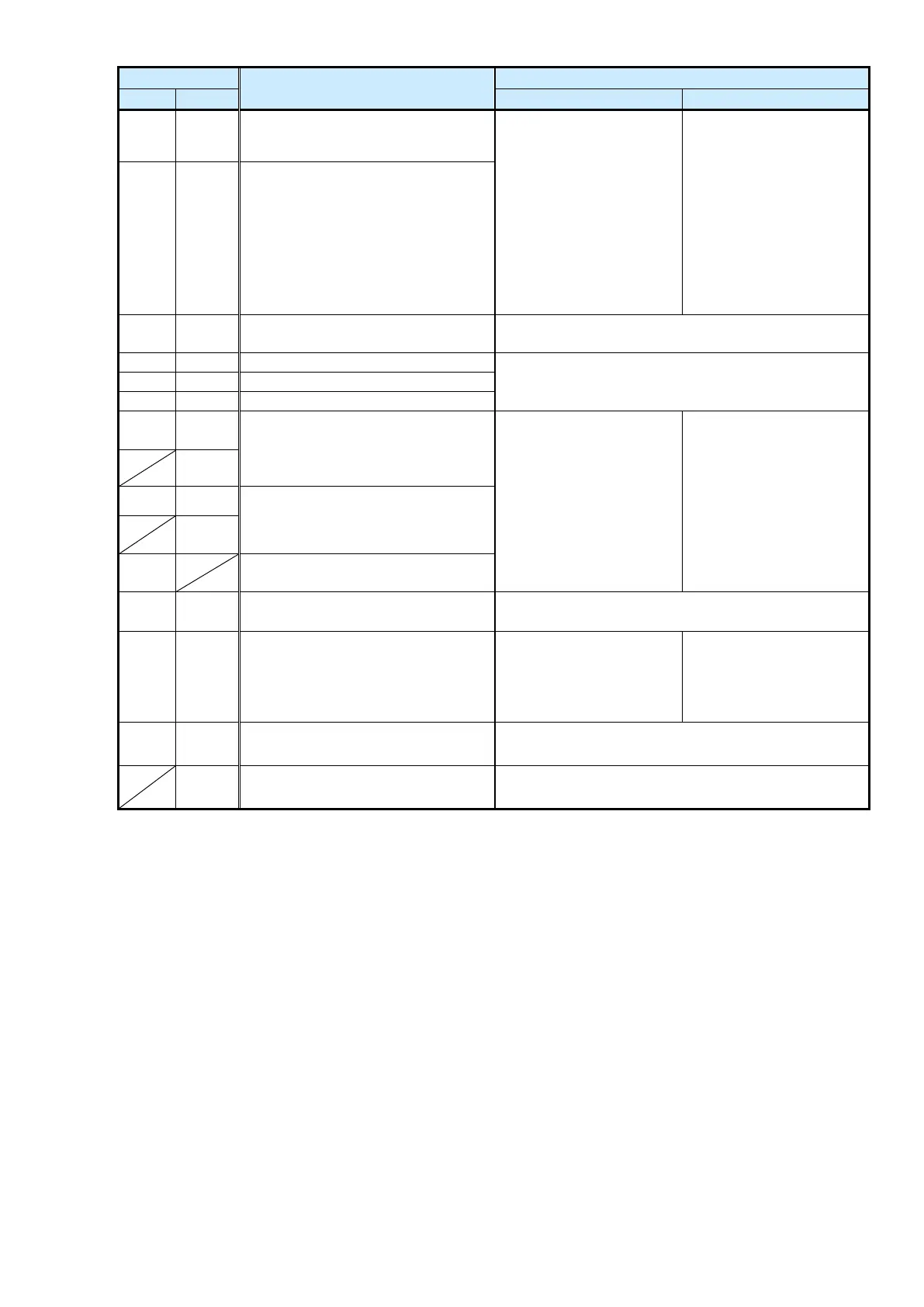
V1000: Frequency Agree
GA500: Frequency (Speed) Agree
C2
*8
PC
*8
Photocoupler output common
MP
MP
Pulse Train Output
*10
32kHz max.
AM
AM
Multi-function analog monitor 1
*11
0 to +10 V
2 mA maximum
0 to +10 V/0% to 100%
4 to 20 mA (receive-
side recommended
impedance: 250Ω)
*12
AC
AC
Monitor common
0 V
PS
External 24 V power supply input
Supplies backup power to the drive control circuit, keypad,
and option board. 21.6 VDC to 26.4 VDC, 700 mA
*1: When replacing the wiring to SC terminal of the V1000 with that of the GA500, see the connection diagram in Table 7.
*2: Factory default = Sinking Mode: SC
*3: Factory default = Sinking Mode: SN (short-circuit SC-SP)
*4: To select the input method, use DIP switch S1 and H3-09 [Terminal A2 Signal Level Select].
*5: Remove the jumper between H1 and HC to use the Safe Disable input.
*6: Minimum OFF width: Time from the Safe Disable input to the output shut-off.
*7: Remove the jumper between H1-HC and H2-HC to use the Safe Disable input.
*8: The wiring to the V1000 PC terminal should be connected to the GA500 C1 or C2 terminal.
*9: Connect a flywheel diode when driving a reactive load such as a relay coil. Make sure that the flywheel diode rating is not
lower than the circuit voltage.
*10: Factory default = Output frequency
*11: Factory default = Output frequency
*12: Use jumper switch S5 and H4-07 [Terminal AM Signal Level Select] to set the signal type.

Other manuals for YASKAWA V1000

Questions and Answers:

Question and Answer IconNeed help?

Do you have a question about the YASKAWA V1000 and is the answer not in the manual?

YASKAWA V1000 Specifications

General IconGeneral
Input Voltage3-Phase 200-240VAC, 3-Phase 380-480VAC
Output Voltage3-Phase 200-240VAC, 3-Phase 380-480VAC
Output Frequency0-400 Hz
Control MethodV/f control
Overload Capacity150% for 60 seconds
Protection FunctionsOvercurrent, Overvoltage, Undervoltage, Overheating, Short Circuit, Ground Fault
Communication OptionsModbus RTU
Ambient Temperature-10 to +50°C (14 to 122°F)
Storage Temperature-20°C to +65°C (-4°F to 149°F)
Humidity95% (non-condensing)
Cooling MethodForced Air Cooling
EnclosureIP20

Related product manuals