User Constant Tables
5-75
* The factory setting depends upon the Inverter capacity. The value for a 200 V Class Inverter of 0.4 kW is given.
Copy Function: o3
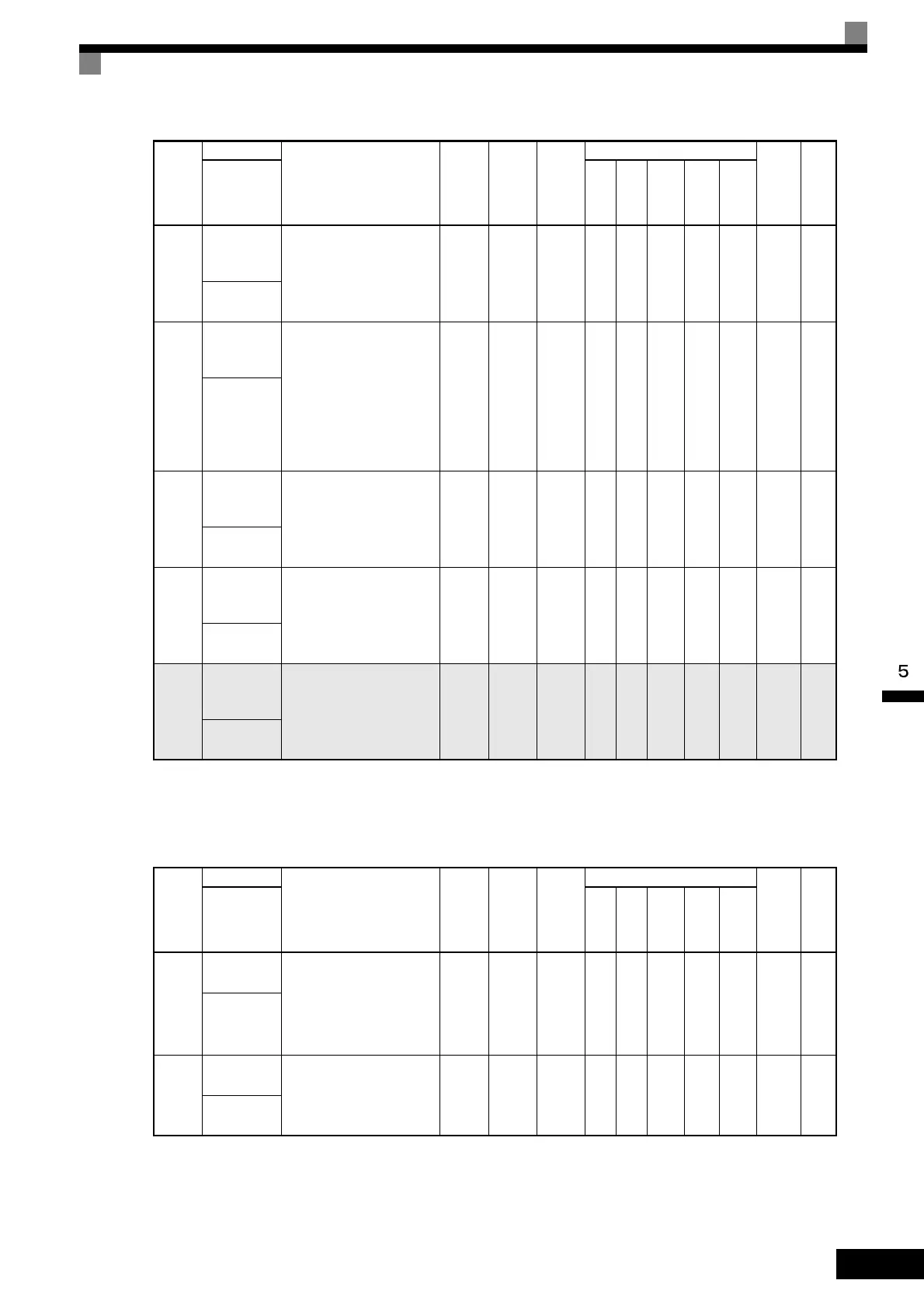
User constants for the copy function are shown in the following table.
o2-07
Cumulative
operation
time setting
Sets the cumulative operation
time in hour units.
Operation time is calculated
from the set values.
0 to
65535
0 hr No A A A A A 50BH
6-144
Elapsed Time
Set
o2-08
Cumulative
operation
time selection
0: Cumulative time when the
Inverter power is on. (All
time while the Inverter
power is on is
accumulated.)
1: Cumulative Inverter run
time. (Only Inverter
output time is
accumulated.)
0 or 1 0 No A A A A A 50CH -
Elapsed Time
Run
o2-10
Fan opera-
tion time set-
ting
Set the initial value of the fan
operation time using time
units.
The operation time accumu-
lates from the set value.
0 to
65535
0 hr No A A A A A 50EH
6-144
Fan ON Time
Set
o2-12
Fault trace/
fault history
clear function
0: Disabled (U2 and U3 con-
stants are on hold.)
1: Enabled (Initializes U2
and U3 constants.)
0 or 1 0 No A A A A A 510H -
Fault Trace
Init
o2-14
Output power
monitor clear
selection
0: Holds output power moni-
tor.
1: Initializes output power
monitor. (Returns to 0.)
0 or 1 0 No A A A A A 512H 5-80
kWh Moni-
tor Init
Con-
stant
Number
Name
Description
Setting
Range
Factory
Setting
Change
during
Opera-
tion
Control Methods
MEMO
BUS
Regis-
ter
Page
Display
V/f
V/f
with
PG
Open
Loop
Vec-
tor
1
Flux
Vec-
tor
Open
Loop
Vec-
tor
2
o3-01
Copy func-
tion selection
0: Normal operation
1: READ (Inverter to
Operator)
2: COPY (Operator to
Inverter)
3: Verify (compare)
0 to 3 0 No A A A A A 515H
6-146
Copy Func-
tion Sel
o3-02
Read permit-
ted selection
0: Read prohibited
1: Read permitted
0 or 1 0 No A A A A A 516H
6-146
Copy Allow-
able
Con-
stant
Number
Name
Description
Setting
Range
Factory
Setting
Change
during
Opera-
tion
Control Methods
MEMO
BUS
Regis-
ter
Page
Display
V/f
V/f
with
PG
Open
Loop
Vec-
tor
1
Flux
Vec-
tor
Open
Loop
Vec-
tor
2

 Loading...


