6-48
Changing Stall Prevention Level during Operation Using an Analog Input
If you set H3-09 (Multi-function Analog Input Terminal A2 Function Selection) or H3-05 (Multi-function
Analog Input Terminal A3 Function Selection) to 8 (stall prevention level during run), you can change the stall
level during operation by setting H3-10 (Gain (Terminal A2)) and H3-11 (Bias (Terminal A2)) or H3-06 (Gain
(Terminal A3)) and H3-07 (Bias (Terminal A3).
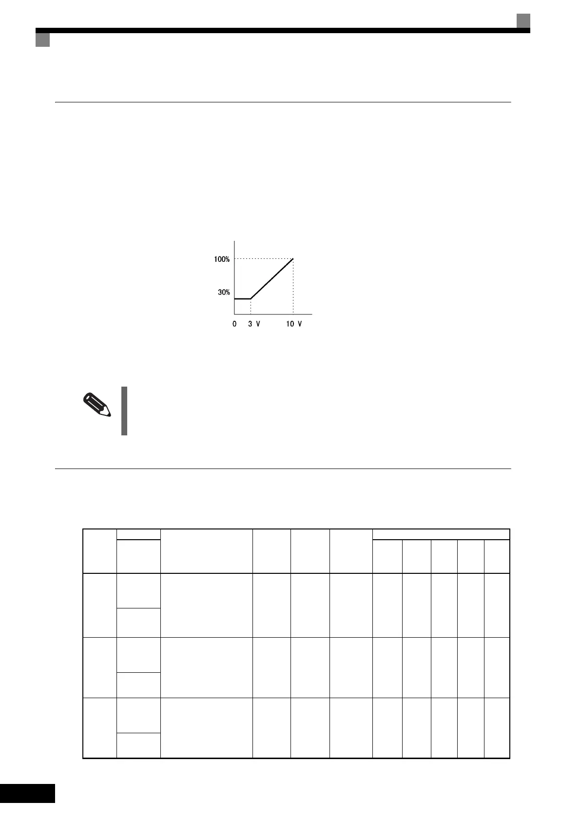
The stall prevention level during operation enabled is the multi-function analog input terminal A2 or A3 input
level or the set value in constant L3-06, whichever is the smaller.
Fig 6.37 Stall Prevention Level during Operation Using an Analog Input
Using Frequency Detection: L4-01 to L4-05
Set these constants when outputting one of the frequency agree or frequency detection signals from a multi-
function output. When using flux vector control, the motor speed is detected.
INFO
If the motor capacity is smaller than the Inverter capacity or the motor stalls when operating at the factory set-
tings, lower the stall prevention level during operation.
User
Con-
stant
Number
Name
Description
Setting
Range
Factory
Setting
Change
during
Operation
Valid Access Levels
Display
V/f
Control
V/f with
PG
Open-
loop
Vector
1
Flux
Vector
Open-
loop
Vector
2
L4-01
Speed agree
detection
level
Set the speed that you want
to detect in Hz.
The set speed is an absolute
value, so the speed is
detected in forward or
reverse.
0.0 to
400.0
0.0 Hz No A A A A A
Spd Agree
Level
L4-02
Speed agree
detection
width
Set the speed detection
range in Hz.
0.0 to
20.0
2.0 Hz No A A A A A
Spd Agree
Width
L4-03
Speed agree
detection
level (+/−)
Set the speed that you want
to detect in Hz.
Set positive values for for-
ward, negative values for
reverse.
−400.0 to
+400.0
0.0 Hz No A A A A A
Spd Agree
Lvl +−
Stall prevention level during operation
Multi-function analog input
terminal A2, A3 input level
(4 mA) (8.8 mA) (20 mA)

 Loading...


